DOB 1300-1556 | X3-45 Commuter PA-1648 Maintenance Manual Section 01 revised Jan 2021
2.6 POWER PLANT ASSEMBLY REMOVAL
To access the engine or engine-related
components, the vehicle power plant assembly
must be removed as a whole unit by means of a
slide-out cradle. The power plant assembly
includes the engine, transmission (including
retarder), alternator and transmission oil cooler.
Remove the power plant assembly as follows:
CAUTION
Tag hoses and cables for identification before
disconnecting in order to facilitate reinstallation.
Plug all openings to prevent dirt from entering
the system.
No parts within the EECU are serviceable. If
found defective, replace the EECU as a unit.
• First
1. Close the heater line shut-off valves.
2. Disconnect batteries from the starting
system by removing battery cables. With
the electrical circuit disrupted, accidental
contact with the starter button will not
produce an engine start.
WARNING
Due to the heavy load of the rear bumper
assembly, it must be adequately supported
before attempting to remove it.
3. Remove the rear bumper assembly
complete with hitch if applicable from the
vehicle. Refer to Section 18, BODY, under
"REAR BUMPER REMOVAL".
4. Using the quick-connect drain hose, drain
the engine cooling system. Refer to
Section 05, COOLING under "DRAINING
COOLING SYSTEM".
• Begin With Vehicle Raised
1. Using a vehicle lift or jack, raise vehicle to
access transmission fasteners and wire
harness.
2. From under the vehicle, disconnect the
propeller shaft as detailed in Section 09,
under heading "Propeller Shaft Removal”.
3. Partially remove L.H. side transmission
protective panel to access connectors.
4. Disconnect transmission harness from
transmission housing.
5. Disconnect steel-braided airline from
pressure regulator output. The pressure
regulator is mounted in the upper section
of the engine compartment backwall and
is accessible through the engine
compartment R.H. side door.
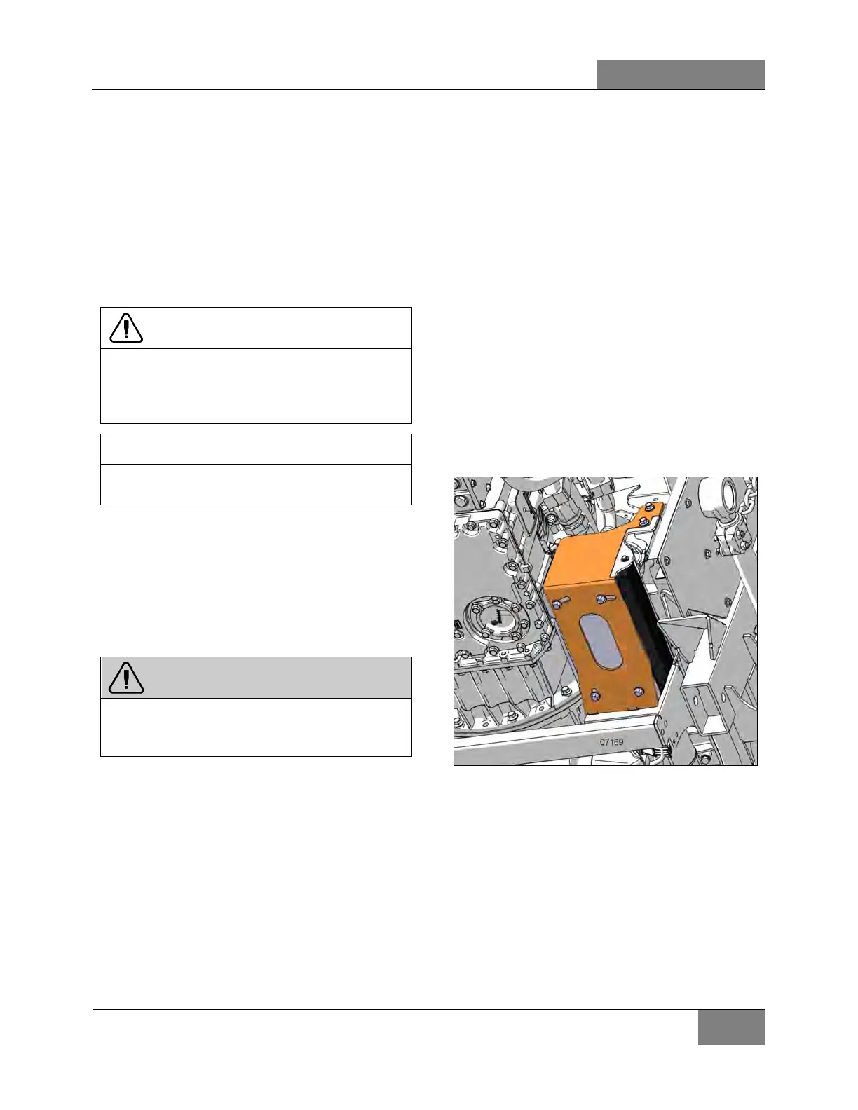
6. Locate the transmission oil cooler beside
the transmission on the driver side.
Untighten bolts A, B, C and D and pivot
the transmission oil cooler towards the
transmission.
FIGURE 12: COOLER POSITION DURING ENGINE
CRADLE INSERTION OR REMOVAL
7. Remove the retaining bolts, washers and
nuts securing the power plant cradle to
the vehicle rear subframe.
8. Disconnect the engine coolant hose near
the starter.
9. Disconnect air compressor suction and
discharge hoses.
 Loading...


