DOB 1300-1556| X3-45 Commuter PA-1648 Maintenance Manual Section 23 revised Nov 2021
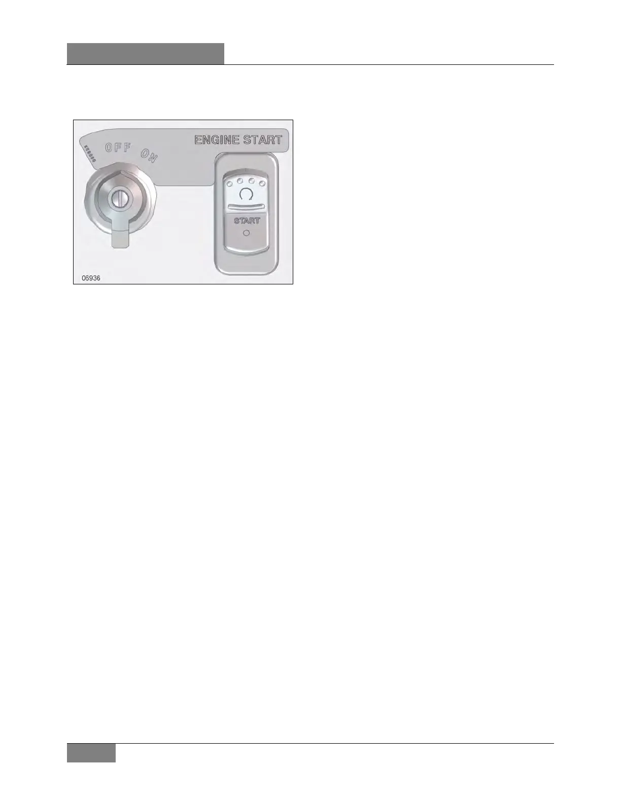
• Perform this switch sequence: ON -
OFF - ON (within 2 seconds) then
START the vehicle.
FIGURE 11: IGNITION SWITCH
5.2 CHECKOUT PROCEDURE
Pre-Trip
• Verify the Display panel indicates system
“OK”.
o Display is illuminated constant white.
o Fire Extinguisher with OK icon and
MENU button is displayed.
• Verify the time and date are correct.
General
• Verify that no obvious physical damage or
condition exists that might prevent system
operation.
Display Panel
• Verify the indicator screen displays the
‘System OK’ screen.
Manual Activation Switch
• Verify that the tamper seal is intact and
access to the switch is unobstructed.
Fire Detectors
• Optical
o Verify that the status lamp on the
detector face is on solid green.
o Verify that nothing is blocking the
detector’s field of view.
o Verify that the windows on the face of
the detector are free of excess
contamination (dirt, oil, grease, etc.) – if
necessary, clean using a water soaked
non-abrasive towel.
o Verify there is no physical damage or
corrosion to the detector’s housing, wire
leads, or any of the 3 windows on the
face of the detector.
• TLSE detector (Module and element)
o Verify the status lamp on the face of the
TLSE Module is illuminated solid green.
o Verify the electrical connections of the
TLSE module and element have no visi-
ble damage and all connections are se-
cure.
o Verify the element has no visible damage
or wearing and is properly held in place
via the mounting clamps. If wear is
found, adjust the positioning of the ele-
ment so that it will not touch adjacent
components and eliminates the point of
wear. Replace the element if it is cut or if
internal material can be seen.
o Visually examine the element to make
sure that it is not twisted. If the element is
twisted, the sheath will not be smooth. If
found, replace the element.
o Visually examine the element’s booted
ends and pigtail wiring for damage.
o Verify the element’s ground wire connec-
tion at each terminal lug end is not loose,
damaged, or missing.
Electrical Harness
• Verify that electrical connectors and electrical
wiring have no visible damage and all
connectors are securely seated.
Extinguisher & Distribution System
• Verify that the extinguisher pressure gage
pointer is in the green arc at room
temperature.
• Verify that distribution piping and nozzles are
intact and unobstructed and that nozzle blow-
off caps are in place.
• Visually inspect the extinguisher for damage
such as pits, gouges, dents, or corrosion.
Have the extinguisher evaluated by a
 Loading...


