DOB 1300-1556 | X3-45 Commuter PA-1648 Maintenance Manual Section 06 revised release October 2021
FIGURE 69: AIM INSPECTION LIMITS FOR UPPER-BEAM
HEADLAMPS
7. The inspection limits in the vertical direction
for low-beam headlamps or the low beam of
a dual-beam headlamp, shall be as
described in Table 1. In the horizontal
direction, the left edge of the high-intensity
zone shall be located from 10 cm (4 in) left
to 10 cm (4 in) right of the vertical centerline
of the beam. The viewing screen shall be
located 7.6 m (25 ft) in front of the vehicle
(Figure 70).
FIGURE 70: AIM INSPECTION LIMITS FOR LOWER-
BEAM HEADLAMPS
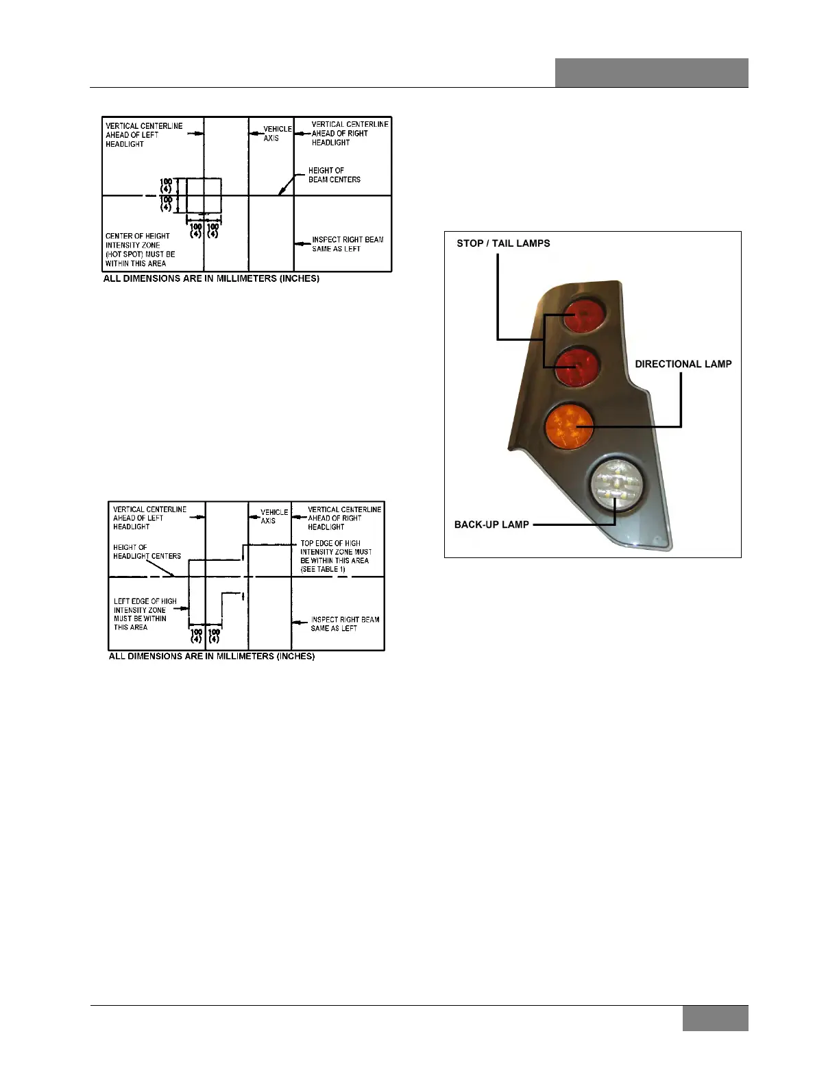
15.4 STOP, TAIL, DIRECTIONAL, BACK-UP,
AND HAZARD WARNING LIGHTS
A combination stoplight, taillight, directional
signal light and back-up light assembly is
mounted at the rear, on each side of the vehicle.
Furthermore, when braking, two center
stoplights (LED) and a center high-mounted stop
light (CHSL) (LED) will illuminate simultaneously
with the stoplights on the sides for increased
safety. The L.H. and R.H. side center stop lights
are also used as directional signal and marker
lights.
The stop, tail, directional signal and back-up
lights consist of individual lamps, each equipped
with 6 LED lights, mounted together as a
module.
LED lights are not replaceable and each lamp is
serviced individually as a complete unit.
The hazard warning flashing system uses the
front, side and rear directional lights
simultaneously. This system is energized by a
switch on the L.H. dashboard.
FIGURE 71: REAR TAIL LAMPS, SOME VEHICLES MAY
HAVE THE DIRECTIONAL LAMP MAY BE MOUNTED ON
TOP POSITION
15.4.1 Lamp Removal and Replacement
1. Open engine compartment rear door.
2. Remove the lamp pod from the engine
compartment door by unscrewing the Torx
hold down screws (4) at the back of the door
and the two (2) side retaining nuts.
3. Remove the lamp support retaining screws
(2), and then from the outside, disconnect
and remove the faulty lamp and its support.
4. From the outside, install the new lamp with
its support then fasten the retaining screws.
5. Reinstall the lamp pod on the door and
reconnect the lamp.
15.4.2 Center Stoplights and Cyclops Light
Removal and Replacement
These (LED) lights are sealed unit and should
be replaced as an assembly in accordance with
the following procedure:
 Loading...


