Mi14-01E Page 5 / 38 Rev: Oct 2021
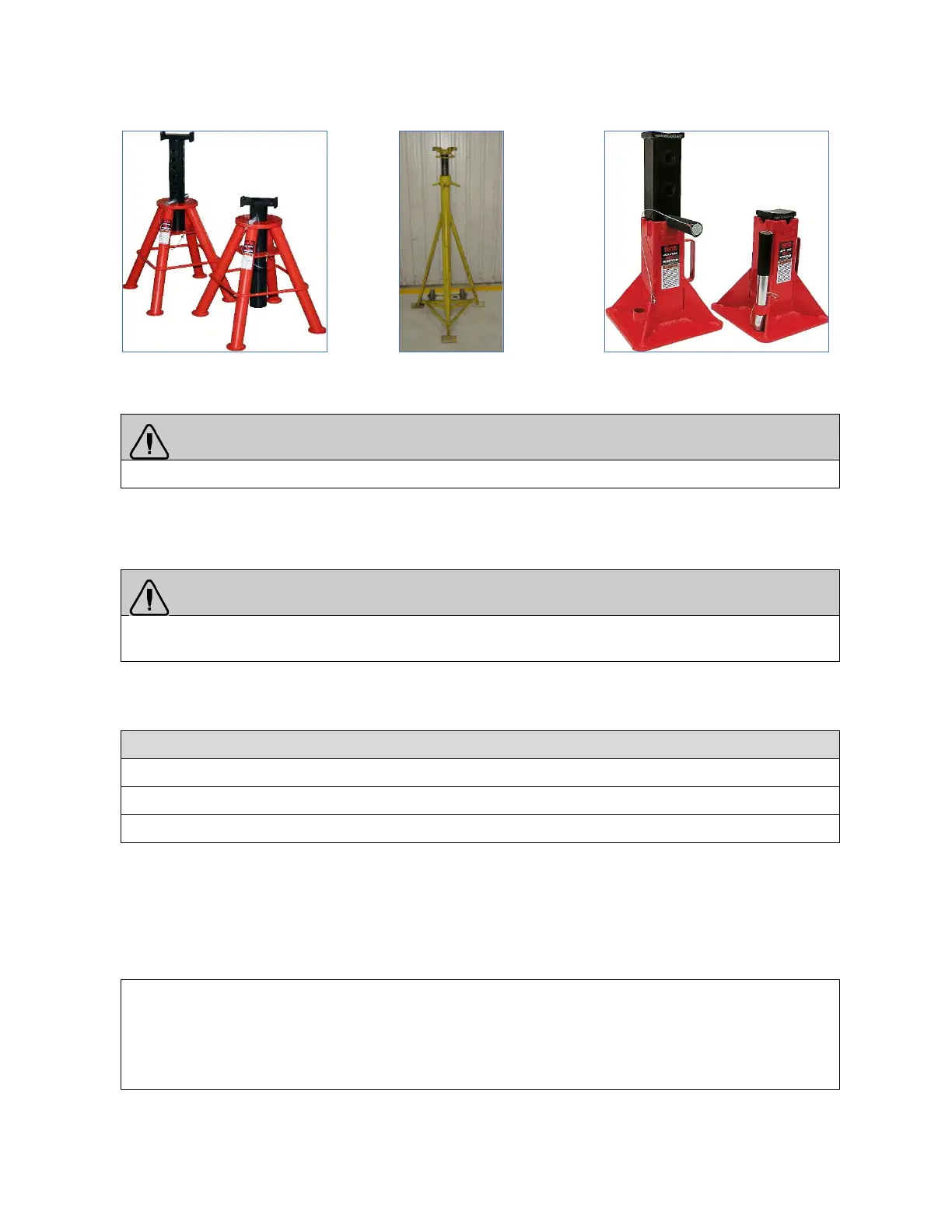
FIGURE 9: 10-TON CAPACITY JACK STAND
FIGURE 10: 16500 LBF
FIGURE 11: 20-TON CAPACITY JACK
WARNING
Prior hoisting, park the bus on a level surface and apply parking brake.
The bus can be supported at the chassis hoisting pads (refer to HOISTING AND LIFTING POINTS
diagram). Use a jack stand of 10 tons capacity at each of the four chassis hoisting pads.
WARNING
Hydraulic jacks are intended for lifting only. Do not get under the bus for any reason unless it is properly
supported with safety jack stands.
1.3 AXLES HOISTING POINTS
2 front axle hoisting points (Figure 12 to FIGURE 15)
2 drive axle underframe hoisting points (Figure 16 & Figure 17)
2 hoisting points under the tag axle (tag axle must be unloaded) (Figure 18)
To assure stability, always use the two hoisting points under a specific axle simultaneously.
Two hoisting points are located under the tag axle. Using the tag axle as rear hoisting points for the vehicle
should be avoided. When possible, use the drive axle as hoisting point.
The vehicle can be lifted from the front axle and the drive axle underframe using lifting equipment of
appropriate capacity.
APPROXIMATE WEIGHT PER AXLE
vehicle supported at front axle and drive axle underframe
Front axle: 12,000 lb. (5 443 kg)
Drive axle: 26,500 lb. (12 020 kg)
 Loading...


