SECTION 22: HEATING AND AIR CONDITIONING
DOB 1300-1556 | X3-45 Commuter PA-1648 Maintenance Manual First release Oct 2020
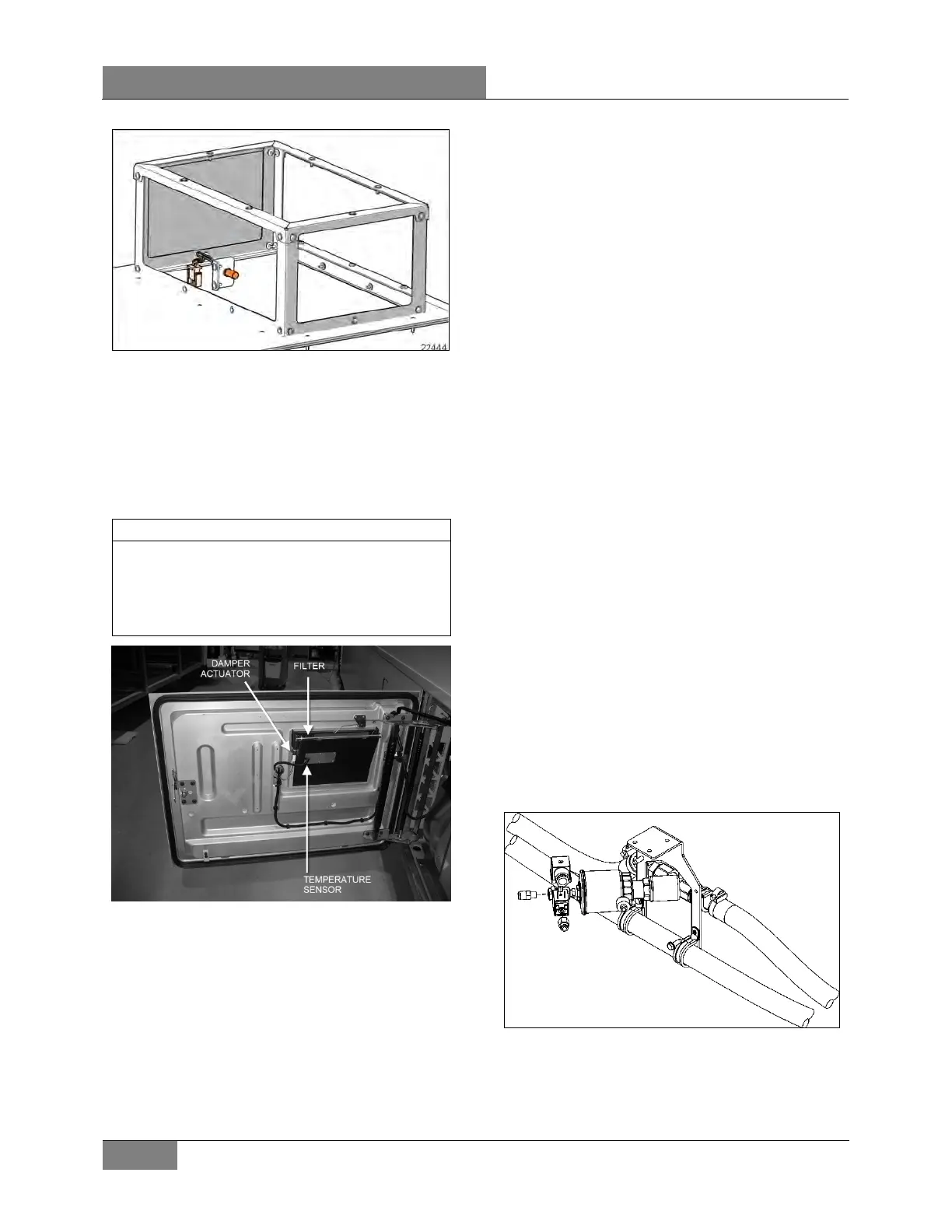
FIGURE 47: TEMPERATURE SENSOR IN PASSENGER
AREA
The flow of water to the vehicle's main heater
core is controlled by a pneumatic water valve
which varies the cycling rate depending on
selected temperature. A red LED, located on
HVAC control unit, illuminates when heating
mode is selected. A green LED illuminates when
compressor clutch is in operation.
The red Heat LED and the green AC LED may
be illuminated at the same time. This indicates
that the temperature control is requesting heat
and the HVAC control is calling for compressor
operation for dehumidification.
FIGURE 48: EVAPORATOR COMPARTMENT 22301
6.5.1 Overhead Compartment Unit
A/C evaporator coils may be added to both
overhead compartment air systems. This air
conditioning unit permits a wider temperature
range in the passenger’s area.
6.6 HEATING
The Figure 3 schematic shows the central HVAC
system heating arrangement.
On coaches, in addition to the normal heating
provided by the engine, an optional preheating
system (104,000 Btu/hr) may have been
installed above the rear wheelhousing on the
L.H. side.
6.6.1 Driver’s Unit Hot Water Pneumatic
Valve
The flow of hot water to the driver's unit heater
core is controlled by a normally open (NO)
pneumatic valve like. The valve located at the
ceiling of the spare wheel compartment
(Figure 49), is designed so that the pilot solenoid
valve, which is part of the assembly, opens and
closes a port which directs air pressure to the
actuator casing, thereby opening or closing the
valve.
When the vehicle is operating without electrical
supply to the pilot solenoid valve, no air
pressure is admitted to the actuator casing, the
cylinder spring pushes up against the cylinder,
thereby keeping the water valve open.
Air pressure at port + 24 V signal at coil =
valve closed
The driver’s unit hot water valve requires a
minimum amount of maintenance. The valve
should be free of dirt sediment that might
interfere with its operation. No other
maintenance is needed unless a malfunction
occurs.
FIGURE 49: DRIVER'S UNIT HOT WATER PNEUMATIC
VALVE ASSEMBLY
 Loading...


