SECTION 09: PROPELLER SHAFT
DOB 1300-1556 | X3-45 Commuter PA-1648 Maintenance Manual (Draft Version – April 2020)
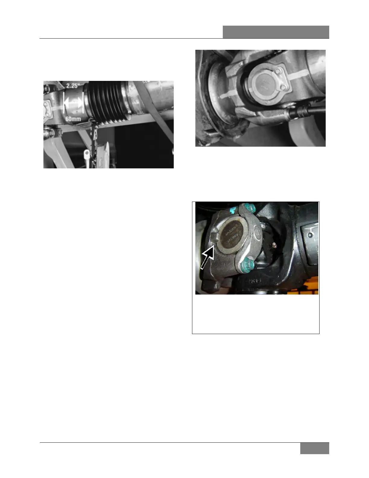
3. Measure and place a mark 2.25 inches (55-
60mm) from yoke shaft shoulder with a
marking stick, paint marker or other legible
marking device.
FIGURE 24: POSITION THE END OF THE BOOT AT THE
2.25 INCHES (55-60MM) MARK MADE ON THE YOKE
SHAFT SHOULDER
4. Position a clamp on each end of the new
boot. Slide the boot onto the grease-free
yoke shaft shoulder.
5. Collapse the boot and insert the yoke shaft
into the splined sleeve, making sure phasing
marks are in line. Position the end of the
boot at the 2.25 inches (55-60mm) mark
made on the yoke shaft shoulder and tighten
boot clamps to the specified torque. Yoke
shaft shoulder must be clean, dry and
grease free.
Failure to properly install and tighten boot
clamps could allow intrusion of
contaminants and can cause driveline failure,
which can result in separation of the
driveline from the vehicle.
6. Before the propeller shaft is completely
installed in the vehicle, slowly collapse and
extend the propeller shaft to make sure the
boot clamps are stationary. If the clamps are
not stationary, recheck for proper clamp
torque. If clamps still are not stationary,
repeat disassembly and assembly
procedure. DO NOT reuse clamps
6.2 PROPELLER SHAFT INSTALLATION
1. Before installing the propeller shaft, inspect
the yoke surface for burrs and damage.
Mating surfaces should be clear of rust,
contamination and grease.
2. With safety straps in place, align the phasing
marks between the yoke and propeller shaft.
FIGURE 25: ALIGN THE PHASING MARKS BETWEEN
THE YOKE AND PROPELLER SHAFT
3. Align the bearing cups with the yoke ears
making sure that the cups are evenly spaced
between the tabs (ears) of the yoke. A soft
faced hammer can be used to fully seat the
bearing cups into the yoke.
FIGURE 26: YOKE TAB (EAR)
Note: Bearing cups must be fully seated
between the yoke tabs (ears). Failure to
seat the cups properly will result in a
premature failure.
4. Install bearing retainers and lock bolts.
5. It is important that the bearing retainer bolts
are torqued in the correct sequence.
Following the diagram below. Torque the
number one bolt before moving to the
number two bolt. Always torque in a counter
clockwise direction starting with the number
one position.
Failure to torque bearing retainer bolts in the
proper sequence could result in premature
failure.
 Loading...


