SECTION 22: HEATING AND AIR CONDITIONING
DOB 1300-1556 | X3-45 Commuter PA-1648 Maintenance Manual First release Oct 2020
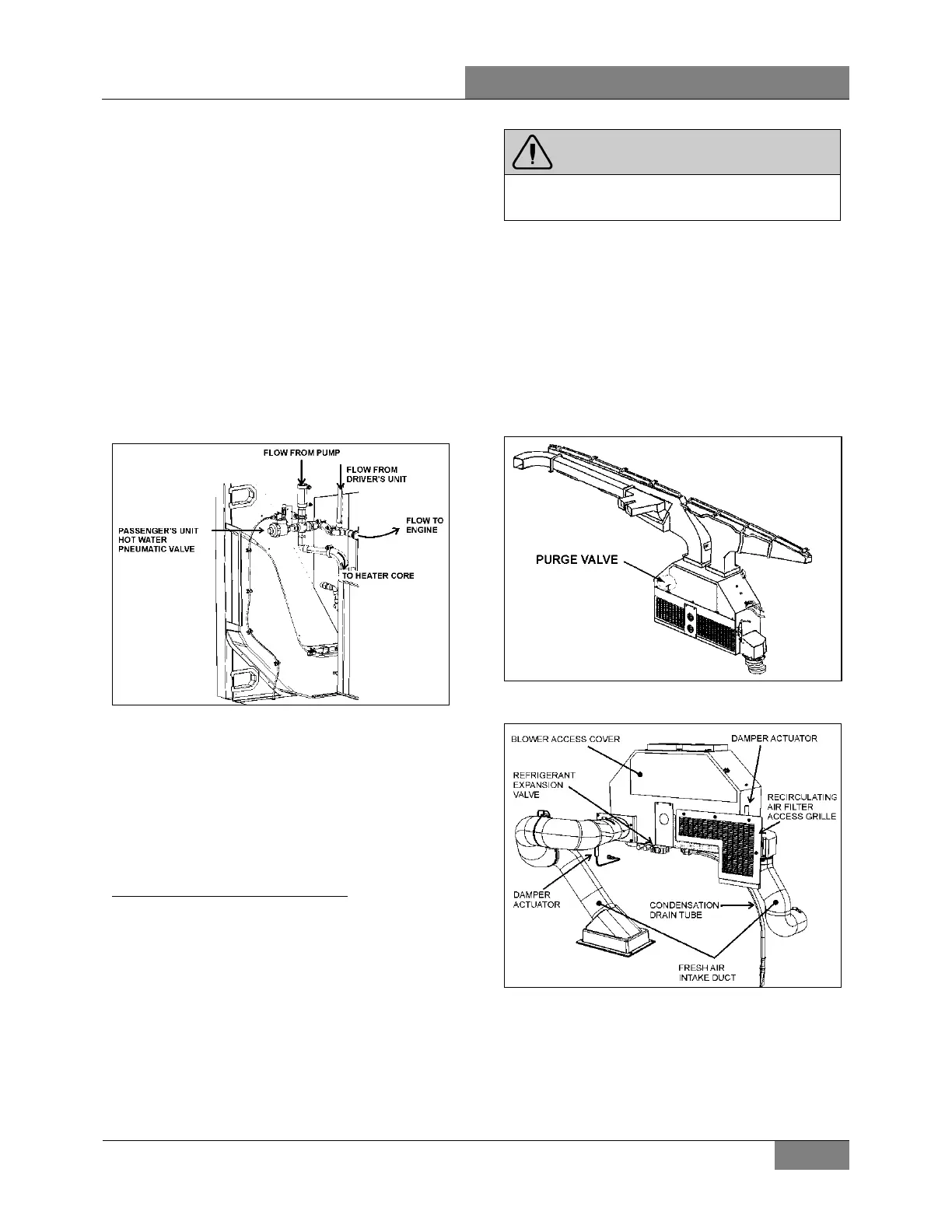
6.6.2 Passenger’s Unit Hot Water Pneumatic
Valve
The flow of hot water to the vehicle’s central
heater core is controlled by a normally open NO
3-way pneumatic water valve assembly (Figure
50). The valve, located in the evaporator
compartment, is designed so that the pilot
solenoid valve, which is part of the assembly,
opens and closes a port which directs air
pressure to the actuator casing, thereby opening
or closing the valve.
When the vehicle is operating without electrical
power to the pilot solenoid valve, no air pressure
is admitted to the actuator casing, the cylinder
spring pushes up against the cylinder, thereby
keeping the water valve open.
FIGURE 50: PASSENGER’S UNIT PNEUMATIC HOT
WATER VALVE ASSEMBLY
22240
6.6.3 Draining Heating System
To drain the entire system, refer to SECTION 05
COOLING SYSTEM. If only the driver’s unit
heater core or passenger’s unit heater core must
be drained, refer to the following instructions.
Draining Driver’s Unit Heater Core
1. Stop engine and allow the engine coolant to
cool.
2. Locate the normally open hot water
pneumatic valve on the ceiling of the spare
wheel compartment (Figure 49), disconnect
its wiring connector, and then connect a 24-
volt external power source, using jumper
cables, to close the valve.
3. Close the hot water lines shutoff valves
located next the engine on the street side
(see Figure 54).
WARNING
Before proceedin
g with the following steps,
check that coolant has cooled down.
3. Loosen hose clamp, install an appropriate
container to recover coolant, and disconnect
silicone hose from hot water pneumatic
valve.
4. From inside the vehicle remove the two
finishing panels in front of the unit. Remove
the three screws fixing the unit front panel.
Open the purge valve located inside the
driver’s unit (Figure 51) to ensure an efficient
draining.
FIGURE 51: DRIVER’S UNIT AIR MIXING BOX 22171PV
FIGURE 52: DRIVER'S HVAC UNIT
 Loading...


