DOB 1300-1556 | X3-45 Commuter PA-1648 Maintenance Manual First release Oct 2020
5. SUSPENSION AIR SYSTEM
The suspension air system has its own air
reservoir (accessory tank) which is located
behind the front axle. Pressurized air from the
main tank (wet tank) flows through a pressure
protection valve (PR-4), to the accessory air tank
and through an air filter which is located in front
service compartment.
The pressure protection valve (PR-4) is mounted
to the supply port of the tank. This valve controls
the pressure at which compressed air is
delivered to the accessory air tank. The valve
remains closed until a preset pressure is
reached (approximately 70 psi (485 kPa)). It then
opens and passes air out the delivery port.
The main use for this valve is to protect the main
air system by ensuring at all times a sufficient air
pressure in the main system (i.e. air delivered to
the accessories will be shut off in case of a
decrease in pressure). Maintenance and repair
information on the pressure protection valve is
supplied in the applicable booklet, annexed to
Section 12, “Brakes and Air System” under
reference number SD-03-2010.
WARNING
Depressurize parts prior to removal.
5.1 INSPECTION
The following inspection should be performed at
established service inspection periods.
Performing these procedures will allow
substandard performance to be discovered
before the condition becomes bad enough to
cause operator complaints or failure during
operation.
1. Visually inspect the suspension air lines for
evidence of chafing on metal parts or other
damage.
2. Visually inspect the air springs for cracks,
abrasion or other damage.
3. Replace any parts found to be damaged.
5.2 AIR LINE TEST
With the main air system at normal operating
pressure, coat all suspension air line
connections and air spring mountings with a
solution of soap and water. Air leakage will
produce soap bubbles. Any leak found must be
corrected as no air leakage is permissible.
6. SUSPENSION HEIGHT ADJUSTMENT
The flow of pressurized air from the accessory
air tank to the air springs is controlled by three
height control valves. These valves are mounted
to the subframe and connected to the axles
through an arm and link connection. This
connection allows the valves to apportion air
pressure in the springs to the vehicle load,
maintaining normal ride height.
To adjust suspension height, refer to
Maintenance Information MI16-14
SUSPENSION HEIGHT ADJUSTMENT USING
HEIGHT CONTROL VALVES included at the
end of this section.
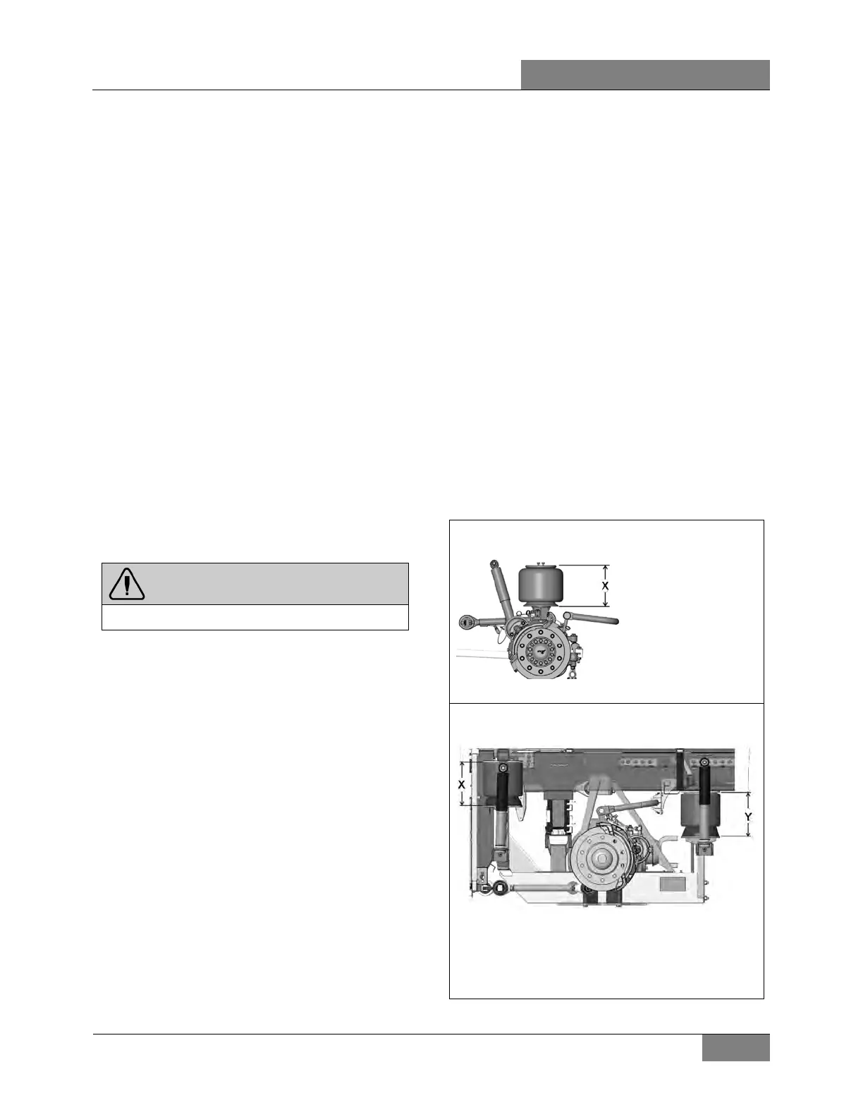
6.1 NORMAL RIDE HEIGHT
The normal ride height is obtained by measuring
and adjusting air spring height of front and rear
suspension.
FRONT SUSPENSION (I-BEAM AXLE)
X = 11 ¾ ± ¼ inch (297 ± 6 mm)
REAR SUSPENSION
FORE AIR SPRINGS
X = 11 ½ ± 1/16 inch (292 ± 1.5 mm)
AFT AIR SPRINGS
Y = 11 ½ ± 1/4 inch (292 ± 6 mm)
 Loading...


