DOB 1300-1556 | X3-45 Commuter PA-1648 Maintenance Manual First release Oct 2020
8 STEERING WHEEL
8.1 REMOVAL
Before undertaking the steering wheel
removal, assure that the front wheels are
pointing straight ahead, aligned with the
vehicle.
1. Set the battery master switch located in the
rear electrical compartment to the "OFF"
position.
2. Pull the horn pad straight up gently to
detach it from the steering wheel (Figure
10).
3. Disconnect the horn wire (white) connected
to the horn pad and the steering wheel
harness 4-pin connector.
FIGURE 10: REMOVING THE HORN PAD
FIGURE 11: STEERING HARNESS & HORN WIRE
4. Unscrew the steering wheel nut. To simplify
installation and ensure steering wheel
alignment, mark the relationship of the
spline shaft to the steering wheel hub (if
marks don’t already exist or don’t line up).
5. Using an appropriate puller, separate the
steering wheel from the spline shaft.
6. From behind the steering wheel, pull gently
on the electrical wires passing through the
rectangular opening in the steering wheel to
finish removal of the steering wheel.
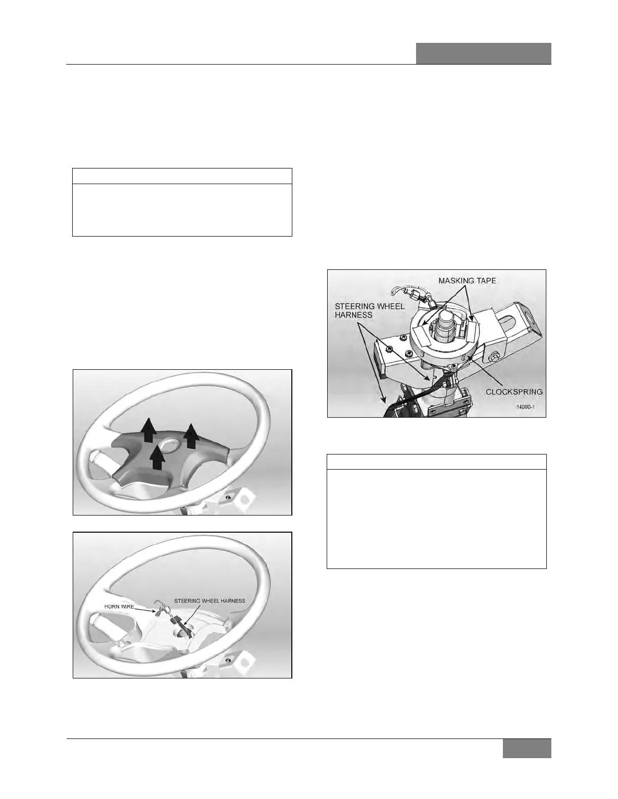
7. Once the steering wheel is removed, it is
important to block any rotating movement of
the clockspring in order to prevent it from
losing its neutral position. Use two pieces of
masking tape to lock it in place (Figure 12).
FIGURE 12: LOCKING THE CLOCKSPRING IN PLACE
The clockspring mechanism permits a certain
number of turns in each direction.
moment of reinstalling the steering wheel, if
the clockspring is not at its neutral position,
the number of available turns will be reduced.
This
may damage the clockspring if the
steering wheel is turned to its maximum
amplitude.
8.2 INSTALLATION
1. Route the white horn wire and the 4-pin
connector through the opening on the
steering wheel.
2. Align the mark on the steering wheel hub
with the mark on the spline shaft and slide
the wheel onto the shaft.
3. Tighten steering wheel retaining nut.
TORQUE : 35-45 lb-ft (47-61 Nm)
 Loading...


