DOB 1300-1556 | X3-45 Commuter PA-1648 Maintenance Manual Section 01 revised Jan 2021
Refer at the beginning section 22 Heating and
air conditioning for torque values.
Refer to MI18-
37 at the end of section 22
Heating and air conditioning for the procedure
of the clutch assembly removal and installation.
Also refer to that document for the compressor
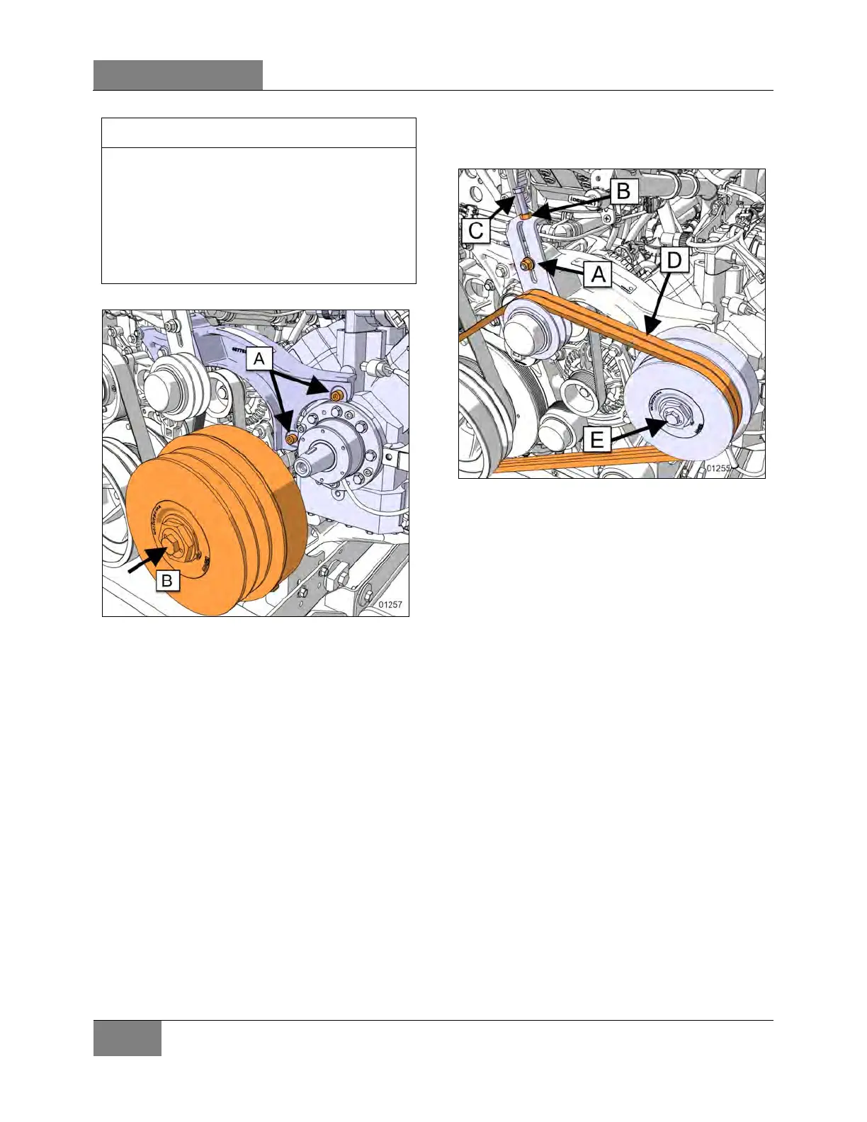
FIGURE 19: CLUTCH ASSEMBLY REINSTALLAT ION
8. Reinstall belts.
9. Apply specific tension to the belt.
FIGURE 20: BELTS REINSALLATION
10. Refill cooling system with saved fluid (refer
to Section 05 coolant system).
11. Once engine fuel system has been drained,
it will aid restarting if fuel filters are filled with
fuel oil (refer to Section 03 fuel system).
12. Start engine for a visual check. Check fuel,
oil, cooling, pneumatic and hydraulic system
connections for leakage. Test operation of
engine controls and accessories.
2.8 ENGINE MOUNTS
The power plant assembly is mounted to the
cradle by means of rubber mounts and
supports.
Two engine support brackets are used at the
front of the engine while two rubber mounts are
mounted at the back of the engine.
It is recommended that new rubber mounts be
installed at each major overhaul.
 Loading...


