DOB 1300-1556 | X3-45 Commuter PA-1648 Maintenance Manual Section 06 revised release October 2021
2.5 SPARE WIRES
When the vehicle leaves the factory, and even in
the case of a fully-equipped vehicle, an
important number of unconnected spare wires
are routed between the junction boxes.
Consequently, for any connection of an
additional accessory, refer to page "Spare wires"
in master wiring diagram to determine the
number, the gauge and location of these wires.
CAUTION
Wire size is calibrated according to the breaker
or fuse that protects it. When using a spare
wire to replace a damaged
the spare wire size is equal or larger than the
wire being replaced. Using a wire too small for
the breaker or fuse amperage might cause
overheating of the wire.
Spare wires are identified by a wire
identification number and by the letters “SP”, to
designate “spare”.
2.6 CIRCUIT BREAKERS
The electric circuits are protected by manual
reset type circuit breakers. The main circuit
breakers (Figure 2), as well as those protecting
the A/C system, are located in the main power
compartment.
This type of circuit breaker de-energizes the
circuit without disconnecting any wire.
Some circuit breakers such as CB2 & CB6 are
different in the fact that you may open the circuit
manually, to do so simply press the blue button
on breaker to open the circuit, repair defective
circuit, and afterwards swing red reset lever of
breaker to close the circuit.
FIGURE 1: BREAKER WITH MANUAL TRIP BUTTON
AND RESET LEVER SUCH AS CB2 & CB6
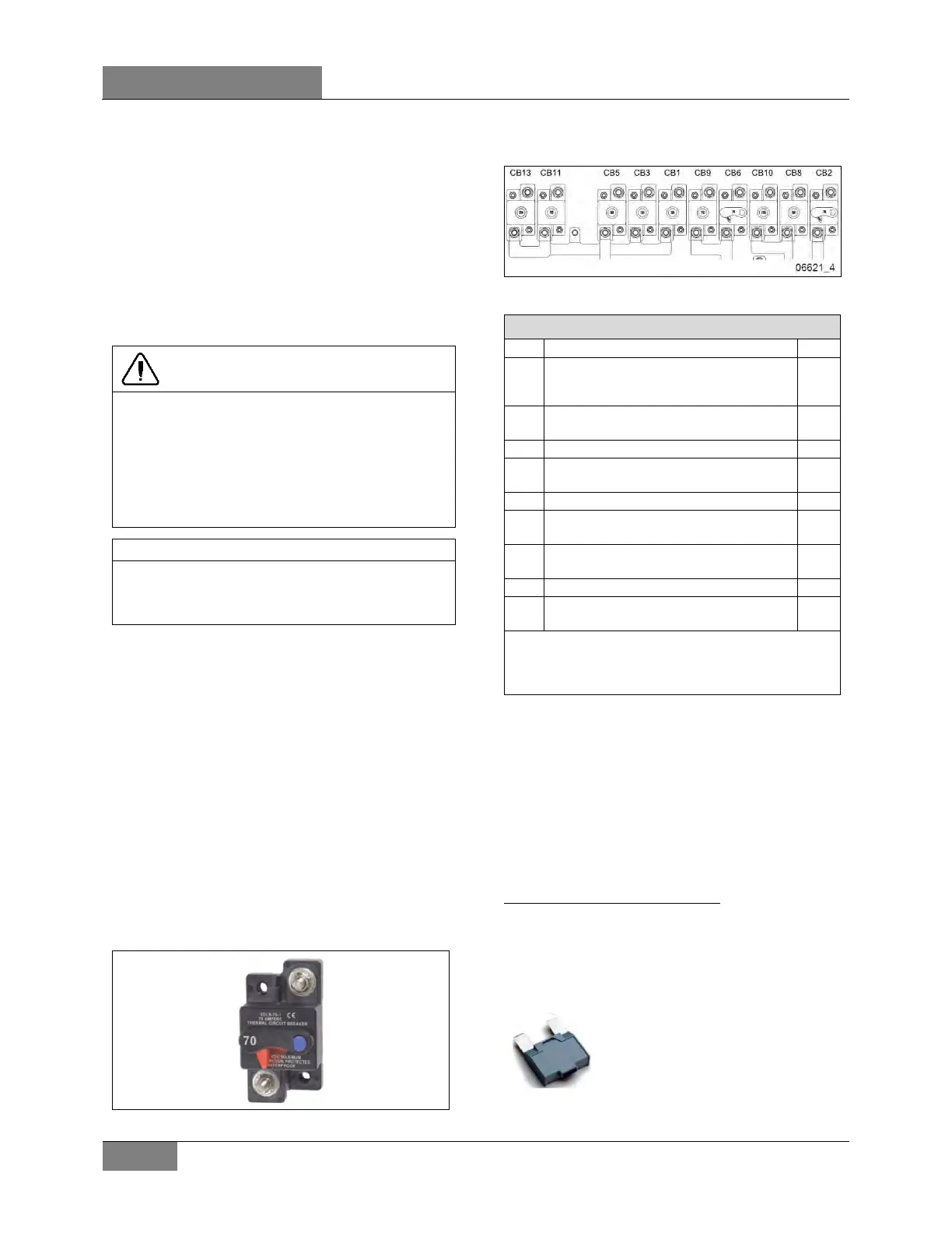
2.6.1 Main Circuit Breakers On Coaches
FIGURE 2: MAIN CIRCUIT BREAKERS ON COACHES
MAIN CIRCUIT BREAKERS ON COACHES
CB1
24 WUP front distribution rear junction box
90 A
CB2
12VD & 12 ECU front distribution – ignition
& engine start rear junction box
70 A
CB3
HVAC evaporator
90 A
CB5
24 WUP rear distribution-rear junction box
90 A
CB6
24VD rear distribution & WCL
rear junction box
70 A
CB8
12 WUP rear distribution-rear junction box
90 A
CB9
24VD preheater
rear junction box
70 A
CB10
12 WUP front distribution – VECF power
rear junction box
150 A
CB11
24 WUP Sound system-rear junction box
50 A
CB13
24 WUP Inverter 120 VAC outlets
rear junction box
150 A
VD= volts direct. The electrical compo
connected to these circuit breakers are direct-
connected to the battery.
2.6.2 VECR/VECF Circuit Breakers
Smaller circuit breakers are located in the VECF
and VECR in front and rear electrical
compartment respectively. Refer to Figure 18
and Figure 20
2.6.3 Electric Cooling Fan Circuit Breakers
MAXI 50 Amp manual reset CB
Each radiator or Charge Air Cooler electric fan
may be protected by a MAXI 50 amp single pole
thermal type breaker with manual reset. If
tripped, the circuit breaker remains open until it
is reset by pressing the reset button.
This type of circuit breaker inserts
in MAXI fuse blades mounting
style. Simply pull the circuit
breaker off the blade type mount
 Loading...


