DOB 1300-1556 | X3-45 Commuter PA-1648 Maintenance Manual Section 06 revised release October 2021
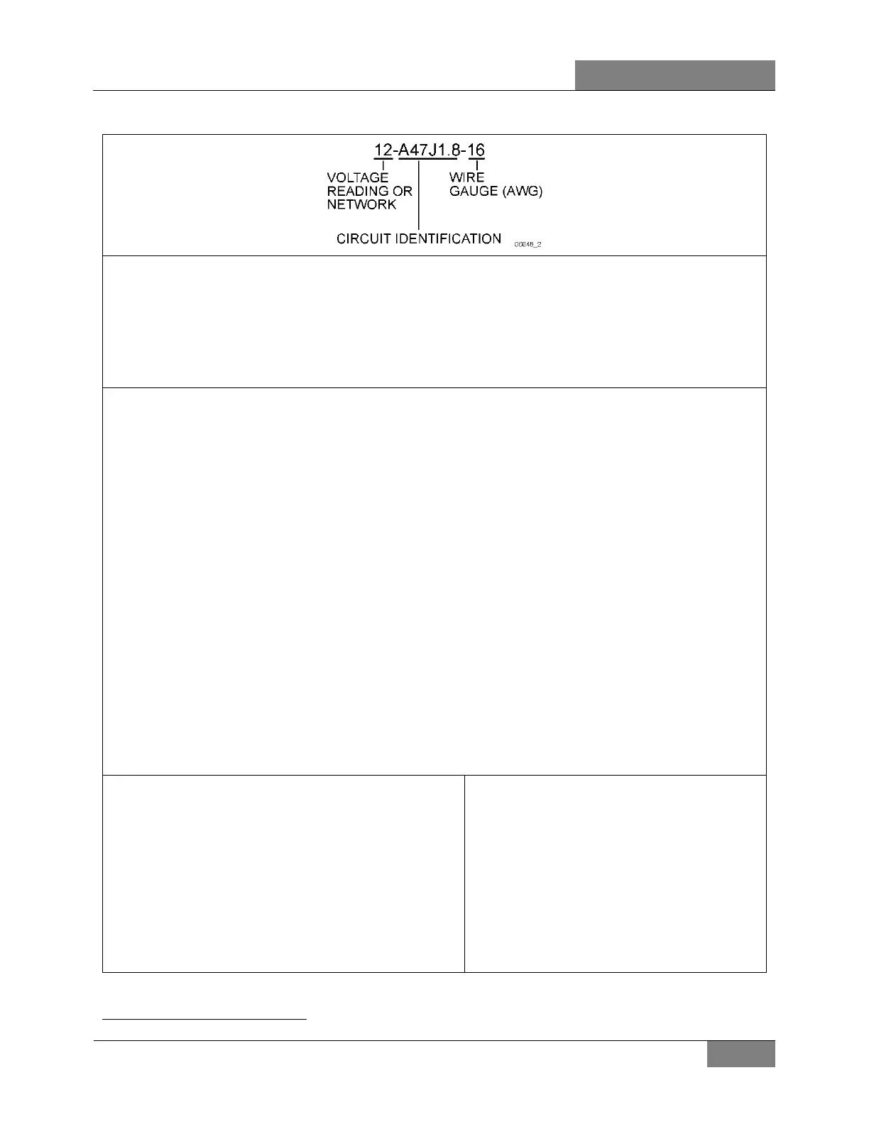
VOLTAGE READING OR NETWORK
CIRCUIT IDENTIFICATION
Ground circuits
Electronic: I/O module number followed by an R, followed by the connector number and pin
number (cavity) (ex: A47RJ1.8, A54 RJ2.14).
Electronic ground studs: Number 00 followed with the stud location
1
and sequential number
(ex: 00R1, 00F4).
Chassis ground studs: Number 0 followed with the stud location and sequential number
(ex: 0EV1, 0FH2).
Power & voltage carrying circuits
Power distribution: Uphill component identification as circuit number
(ex.: F96, CB22).
Multiplex outputs: Output module number and connector and pin number (cavity)
(ex: A55J1.4, A49J2.9)
Relays, diodes, resistors and any other component output: Component number and pin number as
circuit name
(ex: SW55A, R30.87, D12.B).
NETWORKS WIRE GAUGE (AWG)
- DL1 (drivetrain control network)
- DL3 (Dbus Mux)
- DL7 (engine subnet)
- DL9 (engine transmission/I-Shift subnet)
J2284 - DL2
J1587 - DL4 (powertrain subnet 900/901)
1
For stud location, refer to page 2.1 of wiring diagram
 Loading...


