DOB 1300-1556 | X3-45 Commuter PA-1648 Maintenance Manual First release Oct 2020
2. DESCRIPTION
The vehicle is equipped with an Allison B500
automatic transmission
2.1 ALLISON AUTOMATIC TRANSMISSION
The Allison Transmission has 6 speeds with two
top range (fifth and sixth) overdrives.
An electronic control allows the transmission to
shift at exactly the right point on the engine's fuel
consumption curve for best economy. Early
lockup maintains the highest possible mechanical
efficiency through the closely-spaced gear steps,
culminating in two overdrive ratios. This
combination allows progressive shifting
techniques, where engine speeds are reduced for
higher efficiency and lower fuel consumption.
FIGURE 1: ALLISON TRANSMISSION (07075)
Gear selection and torque converter modes are
controlled by a microcomputer-based electronic
transmission management system. It is fed
information regarding throttle position, operator
range selection, engine speed, turbine speed,
transmission output speed and various system
pressures from special electronic sensors. With
this information, it computes shift points and
clutch pressures to meet immediate needs.
Using closed loop adaptive logic, the electronic
control looks at a number of parameters during
the shift, and makes minute adjustments to
match the shift to desired profile stored in its
memory. It then looks at these adjustments and
resets the parameters, which allow the
transmission to quickly compensate for
variations in load, terrain or environment and to
adjust for clutch wear and engine power changes.
A Diagnostic Data Reader can be connected to
the electronic control unit to provide a self-check
of all systems in the transmission. Five-digit
trouble codes greatly reduce the time it takes to
pinpoint potential problems. (Refer to paragraph 7
“Allison transmission troubleshooting” in this
section).
2.1.1 Retarder
This auxiliary braking device for the automatic
transmission is integrated into the basic envelope
of the transmission and transmits its braking force
directly to the propeller shaft. It requires no
additional length and adds only 75 pounds (34 kg)
of weight. Operation of the retarder is controlled
electronically by the driver's use of the brakes.
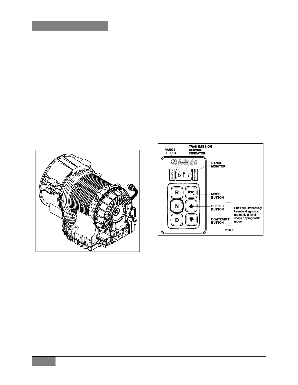
FIGURE 2: ALLISON PUSHBUTTON SHIFT SELECTOR
When activated, fluid enters a cavity and provides
resistance to the turning of rotor blades revolving
with the output shaft. This effectively slows the
vehicle to the point where the service brakes are
needed only for final stopping. The retarder is fully
modulated and is compatible with ABS.
3. ALLISON TRANSMISSION
MAINTENANCE
3.1 MANUAL FLUID LEVEL CHECK
To gain access to the dipstick, open the engine
compartment rear door; dipstick is located on the
radiator side of the engine (Figure 3).
Clean all dirt from around the end of the fluid filler
tube before removing the dipstick. Dirt or foreign
matter must not be permitted to enter the fluid
 Loading...


