DOB 1300-1556 | X3-45 Commuter PA-1648 Maintenance Manual First release Oct 2020
2. Exhaust compressed air from accessory air
tank by opening drain cock under reservoir.
3. Disconnect the height control valve link and
pull down the control arm to ensure all air is
exhausted from air springs.
While performing this step, do not change the
height control valve control arm adjustment.
4. Disconnect air line from air spring, remove
elbow (if applicable), and cover both the line
end and fitting to prevent the entry of foreign
matter.
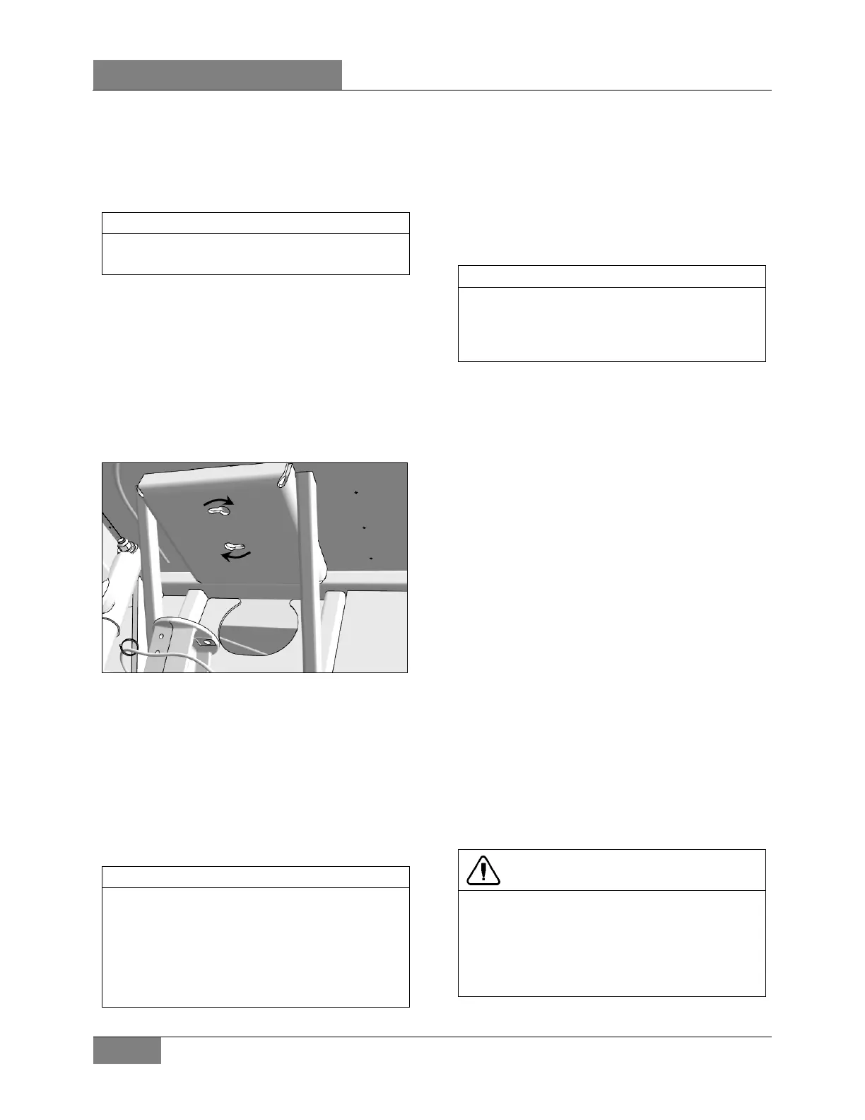
5. Unscrew the two air spring lower mounting
nuts.
6. Rotate the air spring clockwise (Figure 3) to
free the upper attachments from the
mounting plate.
7. Remove the air springs.
FIGURE 3: AIR SPRING UPPER MOUNTING PLATE
3.1.3 Installation
1. Compress air spring as necessary and
position air spring between both the lower
and upper mounting plates.
2. Align the upper attachments with holes in the
mounting plate. Rotate air spring
counterclockwise.
3. Thread the lower nuts a few turns.
To facilitate air spring installation, compress it
manually then put a piece of tape over the air
line threaded fitting. This prevents air from
getting back into the air spring
compressed, thus enabling to place the air
spring
in between the mounting plates and
greatly easing installation.
4. Tighten and torque the lower stud nuts.
TORQUE: 31-38 lb-ft (42-52 Nm)
5. Install elbow (if applicable), then connect air
line.
6. Connect the height control valve link.
7. Build up air pressure in system.
To accelerate this operation, air reservoirs can
be filled from an exterior air supply connected
to the accessory tank fill valve or to the
emergency fill valve.
7. Check operation of bellows and with the
primary air system at normal operating
pressure (122 - 140 psi (841 - 965 kPa)),
coat the air line connections and air spring
mounting areas with a water and soap
solution. Bubbles will indicate an air leak,
and none is permissible. Repair or replace
defective parts.
8. Reinstall wheel.
9. Remove the hydraulic floor jack from under
the axle, then lower vehicle to ground.
3.2 SHOCK ABSORBERS
Double-action, telescoping-type shock absorbers
ensure a smooth ride and enhance vehicle
stability on the road. All shock absorbers are
eye-type mountings. The front and tag axles are
each provided with two shock absorbers while
the drive axle is provided with four of them.
Shock absorbers are non-adjustable and non-
repairable. Maintenance requirements involve
replacement of the rubber mounting bushings,
and tightening of all shock absorber pins
according to Torque Table when shock absorber
replacement occurs. If a shock absorber
becomes inoperative, complete unit must be
replaced.
CAUTION
When a shock absorber is found defective,
always replace
with a new set on affected
axle, except if there has been a recent
replacement of one unit. The following method
will help in determining if both shock absorbers
on the same axle have to be replaced.
 Loading...


