SECTION 13: WHEELS, HUBS AND TIRES
DOB 1300-1556 | X3-45 Commuter PA-1648 Maintenance Manual | Section 13 revised Jan 2022
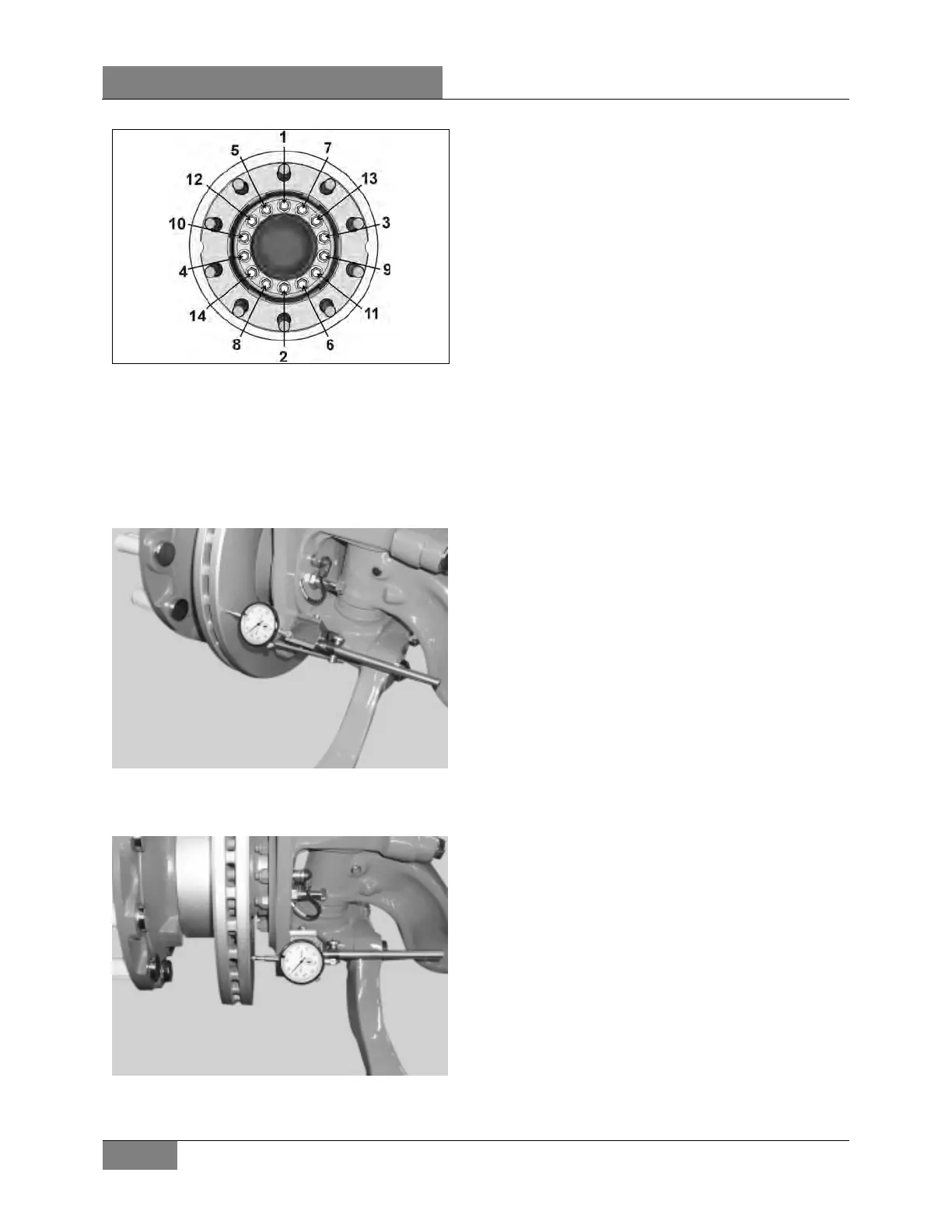
FIGURE 32 HUB FLANGE HEX CAP SCREW
TIGHTENING SEQUENCE
17. Once the hub flange has been correctly
fitted; it is necessary to check the axial run
out of the brake disc.
18. Position a dial test indicator onto the axle in
a suitable position.
FIGURE 33
19. Position the stylus of dial test indicator onto
brake disc as shown.
FIGURE 34
20. Rotate the hub through 360° and note any
movement of the dial test indicator.
THE MAXIMUM RUNOUT IS 0.1 mm / 0.004 in
21. Remove and check out of specification disc
to ensure no damage has occurred to the
mounting faces, or that no dirt is present.
22. Remove any dirt found on the mounting
faces and refit and re check disc.
23. Should it be found that a cleaned and
refitted disc is still out of specification; it
must be replaced.
24. Mount the brake caliper. Refer to Knorr
Bremse manual.
25. Mount the wheel over studs, being careful
not to damage stud threads.
26. Screw in the hex stud nuts (refer to FIGURE
2 for sequence) so that wheel will position
itself concentrically with hub. This is
important, otherwise wheel may be eccentric
with hub and will not run straight. In this
initial step, slightly tighten the nuts to
correctly position the wheel.
27. Tighten stud nuts progressively as shown in
Figure 3. The final tightening should be done
with a torque wrench. Tighten stud nuts.
TORQUE: 450-500 lb-ft (610-678 Nm)
 Loading...


