24
DOB 1300-1556 | X3-45 Commuter PA-1648 Maintenance Manual First release Oct 2020
Position the ball cup halves so the joint
between them lies on the centerline of the arm.
Ensure that the set screws are not on the joint
between the cup halves.
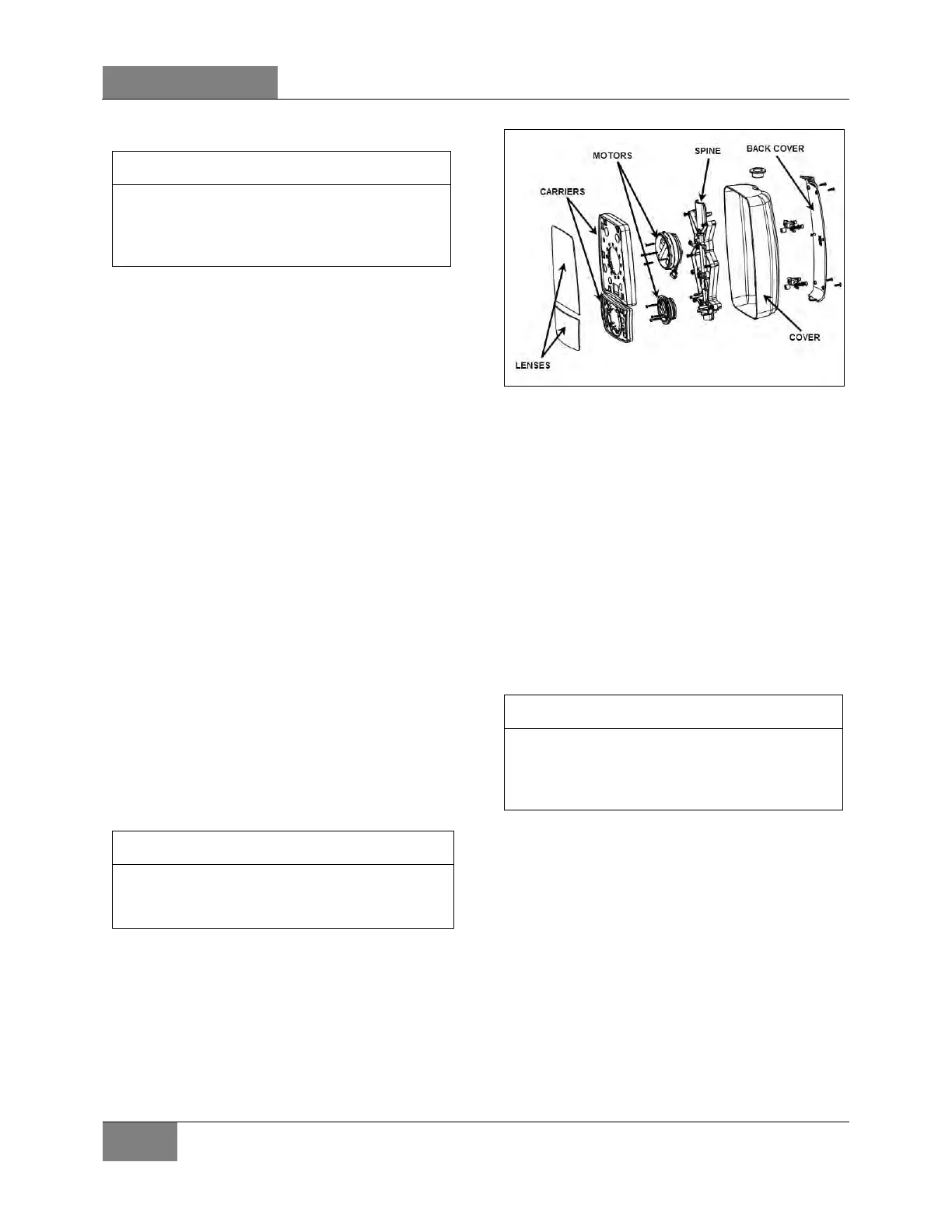
• Remote Controlled Rear View Mirrors
The remote controlled external rear view mirrors
attach to support arms using a pivot collar
secured by set screws. Loosening the set
screws allows the whole head assembly to turn
on the support arm for initial adjustment. A
mounting bolt and washer hold the arm support
to the mounting bracket. The arm support can be
moved to position the mirror head into or away
from the coach body.
• Mirror Control
The remote control pointer knob(s) for the
mirrors is (are) mounted on the L.H. side control
panel. The harness to the mirror head runs
through the arm support. The remote motor is
mounted to the mirror head behind the mirror
glass.
Choose the side to be adjusted by pressing
the “L” (left) or “R” (right) button on the
control pad. The flat mirror is then adjusted
by pressing the “upper” button and the
convex mirror by pressing the “lower”
button. The selected mirror can now be
adjusted left to right or up and down by
using the arrow keys on the control pad. The
R/H side round mirror is non-adjustable.
The mirrors heater function (HTR button and
LED indicator) is optional and not connected on
this vehicle.
• Disassembly
At the end of the mirror arm, loosen the set
screws to relieve tension on the ball stud.
Remove the ball stud. Remove the ball stud from
the arm and gently pull the harness out until the
connector is exposed.
FIGURE 16: R/H OUTSIDE REAR-VIEW MIRROR 18694
Remove the four screws fastening the mirror
arm base to the coach. Slide the harness free of
the mirror arm base.
• Assembly
Attach a stiff wire (snake) to the end of the
harness and insert the wire through the mirror
arm base and arm, gently pull the harness
through the arm and disconnect the "snake".
Connect the mirror head harness. Insert the
harness connector back into the mirror arm.
Insert the ball stud into the mirror arm and
tighten the socket set screws.
Position the ball cup halves so the joint
between them lies on the centerline of the arm.
Ensure that the set screws are not on the joint
between the cup halves.
• Glass removal and installation
Using a non-metallic flat wedge, insert the edge
under the over-hang tab covering the mirror
glass.
Raise the wedge to spread the over-hang tab. By
continuing to raise the wedge, the glass will
begin to pop out.
Do not force the glass further than half an inch
outward. A secondary adhesive holds the glass.
This adhesive is used to cushion the glass and
dampen vibration. It is soft and can be cut fairly
easily.
 Loading...


