13 Detector
13.2
13.
150
GC-2010 Plus
13.2Hydrogen flame ionization detector (FID)
13.2.1 Principle of FID operation
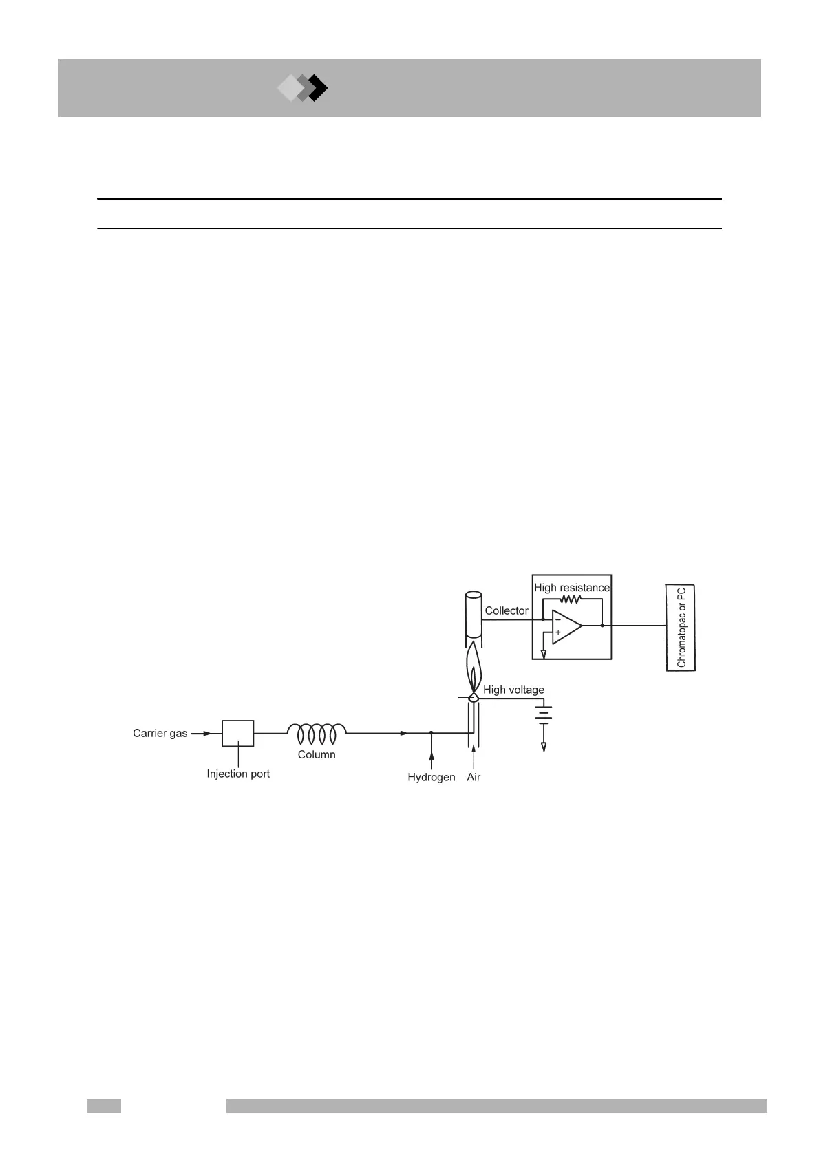
In the hydrogen flame ionization detector (FID), hydrogen gas is mixed with the column
outlet gas at a certain ratio and then the gas mixture is combusted in the air atmosphere as
shown in Fig. 13.2.1. DC voltage is applied on the jet. A collector is located on the upper
area of the FID. When only pure carrier gas (nitrogen, helium, or argon) and hydrogen gas
are mixed, almost no current is produced between the FID jet and collector. When carrier
gas containing an organic compound, which is sample components injected into the injection
port and then separated by the column, is discharged from the FID jet, current is produced
between the FID jet and collector proportionally to the amount of the organic compound.
This is because ions (mainly carbon ions) are generated when an organic compound
combusts within the hydrogen flame and the generated ions are captured by the collector.
For isomers, the ion quantity generated is almost proportional to the number of carbons
contained in the compound. However, carbon atoms in a “C=O” form do not create a signal.
The presence of halogens in the molecular construction decreases the ion quantity
generated.
Because the ion current obtained by the FID as described above is very low, it is amplified
by an amplifier and then output to a Chromatopac or personal computer as a proper voltage.
Fig. 13.2.1
Jet
Amplifier

 Loading...


