15 Optional Devices
15.3 Setting the AUX APC Parameters
210
GC-2010 Plus
15.3.5 Using restrictor tubing
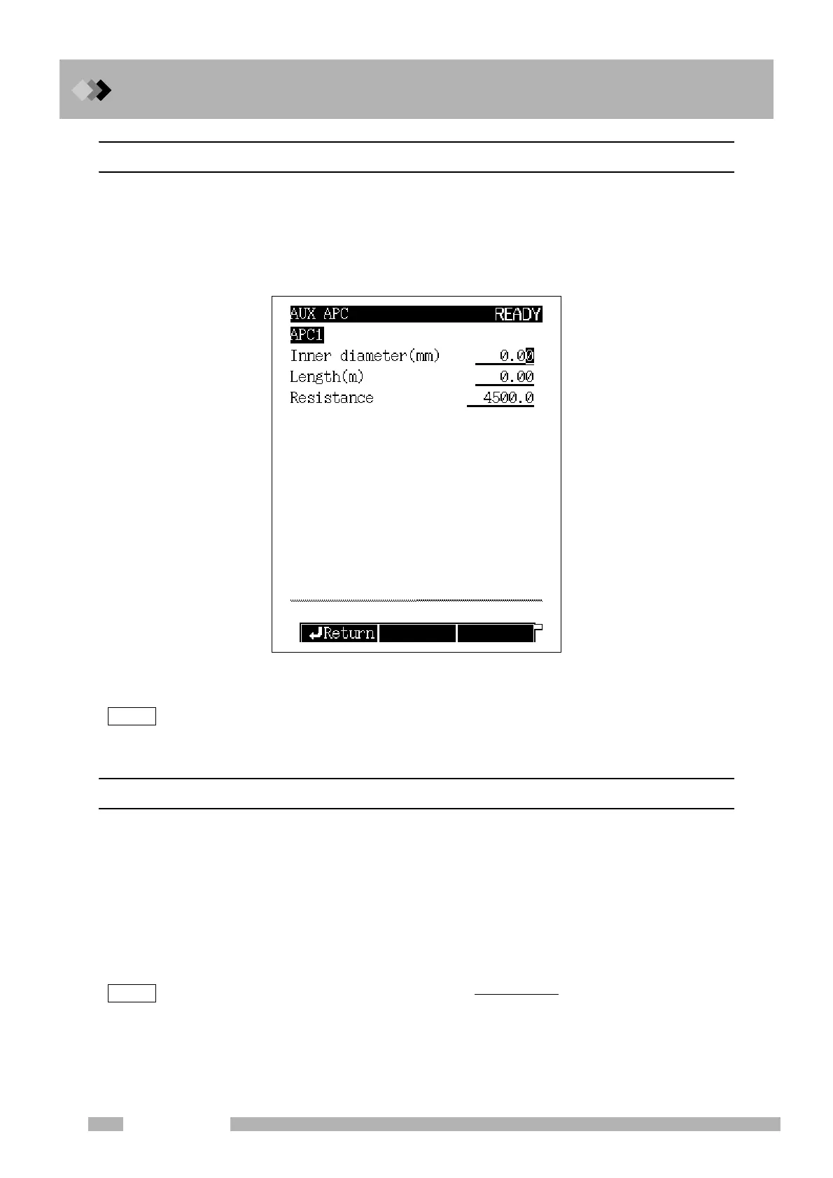
Select the desired APC from the main APC screen. Then press [Resistor] (PF menu) from
the AUX APC main screen to display the restrictor tube setup screen shown in Fig.15.3.3.
The difference between set and actual flow rates can be eliminated by installing a restrictor.
Enter the restricto’s inner diameter, length, and resistance.
NOTE If the necessary pressure to flow rate conversion information is not saved in the GC, the actual and
measured flow rate may still not be equivalent.
15.3.6 Parameter list
INNER DIAMETER
Range: 0.01−6.00 mm, Default: 0.00
LENGTH
Range: 0.1 −250.0 m, Default: 0.00
RESISTANCE
Range: 0.01−100000.0, Default: 1000.0
When the inner diameter and the length have been entered, the resistance is automatically
calculated. Alternatively, enter only the resistance.
NOTE The resistance is calculated according to this formula: ×10
6
.
Resistance valves greater than 10
5
can not be calculated.
The resistance of the restrictor should be smaller than 10
5
, when the “CONTROL MODE” of AUX APC
is FLOW.
Fig. 15.3.3 Restrictor setup screen
(i.d. (mm))
4
length (m)

 Loading...


