12 Injection Port
12.5 Split/Splitless Injection System
132
GC-2010 Plus
12.5.6 Creating a Flow rate program
If the control mode is set to “FLOW”, increase and decrease the total flow rate during
analysis by making a flow rate program.
When you set a flow rate program for the APC, a corresponding pressure program is actu-
ally calculated based on of the pressure-flow rate calibration curve saved by the GC.
12.5.6.1 Screen description
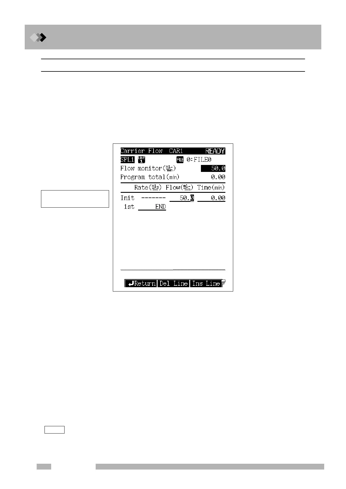
Select [Flow Prog] (PF menu) from the [FLOW] key main screen while the control mode
is set to “FLOW” to display the Carrier Flow screen shown in Fig. 12.5.9.
12.5.6.2 Parameter list
FLOW RATE
Range: 0.00−970.0 ml/min (Refer to Fig. 3.5.1.), Default: 50 ml/min
Set the initial flow rate and the final flow rate for each stage of the total flow rate
program.
TIME
Range: 0.0−9999.99 min, Default: 1.00 min
Set the hold time for the initial flow rate and the final flow rate for each stage of the flow
rate program.
RATE
Range: END/-400.00−400.00 ml/min
2
, Default: END
Set the flow rate program rate.
If you set the rate to “0”, “END” appears and the program finishes at the previous ramp.
If you move the cursor to “END” and set any numeric value other than “0”, the pressure
and the time for that ramp can be entered.
NOTE The control range of the flow rate program may be limited depending on the column in use, purge flow
rate and gas restrictor.
Fig. 12.5.9 Flow rate program setup screen
Up to 7 ramps of flow rate
increase/decrease can be set.

 Loading...


