3 AFC, APC
3.3
3.
35
GC-2010 Plus
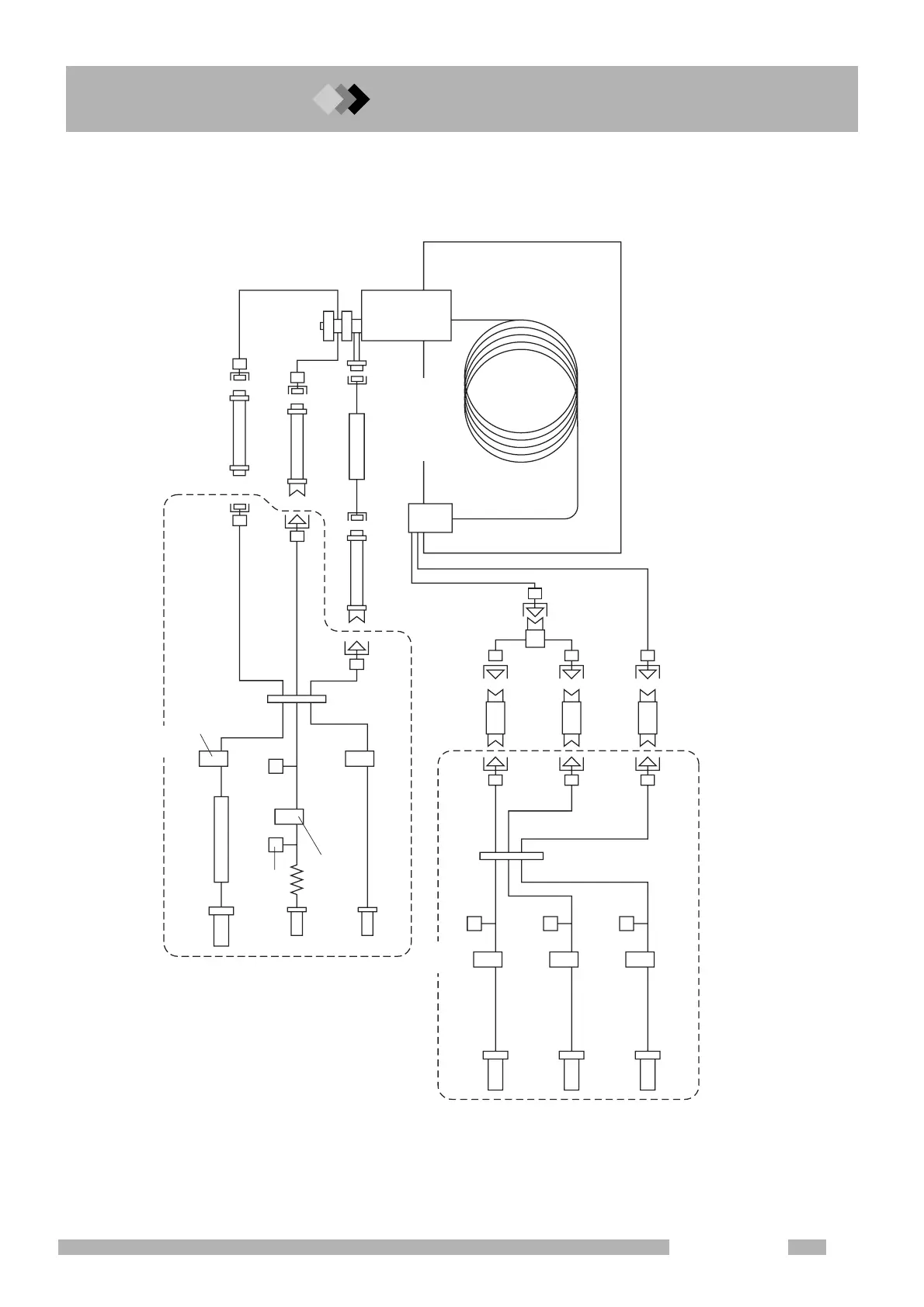
3.3Flow Line Diagram
Fig. 3.3.1
S
CC
PP
H
M
A
H
H
M
A
Note: This figure illustrates an FID or FTD detector example.
For ECD or TCD detectors, the APC controls only the makeup gas.
For FPD detector, the APC controls only hydrogen and air.
CARRIER IN
(GC rear)
H
2
(GC rear)
MAKE UP
(GC rear)
AIR
(GC rear)
PURGE VENT
SPLIT VENT
APC
Column oven
Flow rate sensor
TFC
(Flow rate sensor)
Pressure sensor
Pressure sensor
Pressure sensor
Pressure sensor
Column inlet
pressure sensor
SPC
(Septum Purge Controller)
ESC
(Electronic Split Controller)
Trap
Trap
Molecular sieve filter
Valve for H
2
Valve for makeup gas
Valve for air
H
2
restrictor
Makeup gas restrictor
Air restrictor
Capillary column
Detector
Injection port
TFC:TOTAL FLOW CONTROLLER
SPC:SEPTUM PURGE CONTROLLER
ESC:ELECTRONIC SPLIT CONTROLLER
AFC
FC
TFC
SPC
ESC
PC

 Loading...


