Parameters
List of Parameters
1-146
© Siemens AG 2007 All Rights Reserved
SINAMICS G120 Control Units CU240S, Edition 05/2007
Description: Dynamic braking absorbs the braking energy in a chopper resistor.
This parameter defines the rated duty cycle of the braking resistor (chopper resistor).
Dynamic braking is active when the function is enabled and DC-link voltage exeeds the dynamic braking switch-on
level.
Values: 0: Disabled
1: 5 % duty cycle
2: 10 % duty cycle
3: 20 % duty cycle
4: 50 % duty cycle
5: 100 % duty cycle
Dependency: If dynamic braking is used with DC braking enabled as well as compound braking, DC braking and compound brak-
ing will take priority.
Notice: Initially the brake will operate at a high duty cycle dependant on the DC link level until the thermal limit is
approached.
The duty cycle specified by this parameter will then be imposed.
The resistor should be able to operate at this level indefinitely without overheating.
The threshold for the warning A0535 is equivalent to 10 seconds running at 95 % duty cycle.
The duty cycle will be limited when it was running 12 seconds at 95 % duty cycle.
p1237 Dynamic braking / Dynamic braking
PM240 Access level: 2 P-Group: - Data type: Unsigned16
Quick comm. NO Active: YES Data set: -
Can be changed: C, U, T
Min Max Factory setting
0 5 0
0210p213.1V213.1V
mainsChopper,DC
⋅⋅=⋅⋅=
If p1254 = 0 :
otherwise :
1242r98.0V
Chopper,DC
⋅=
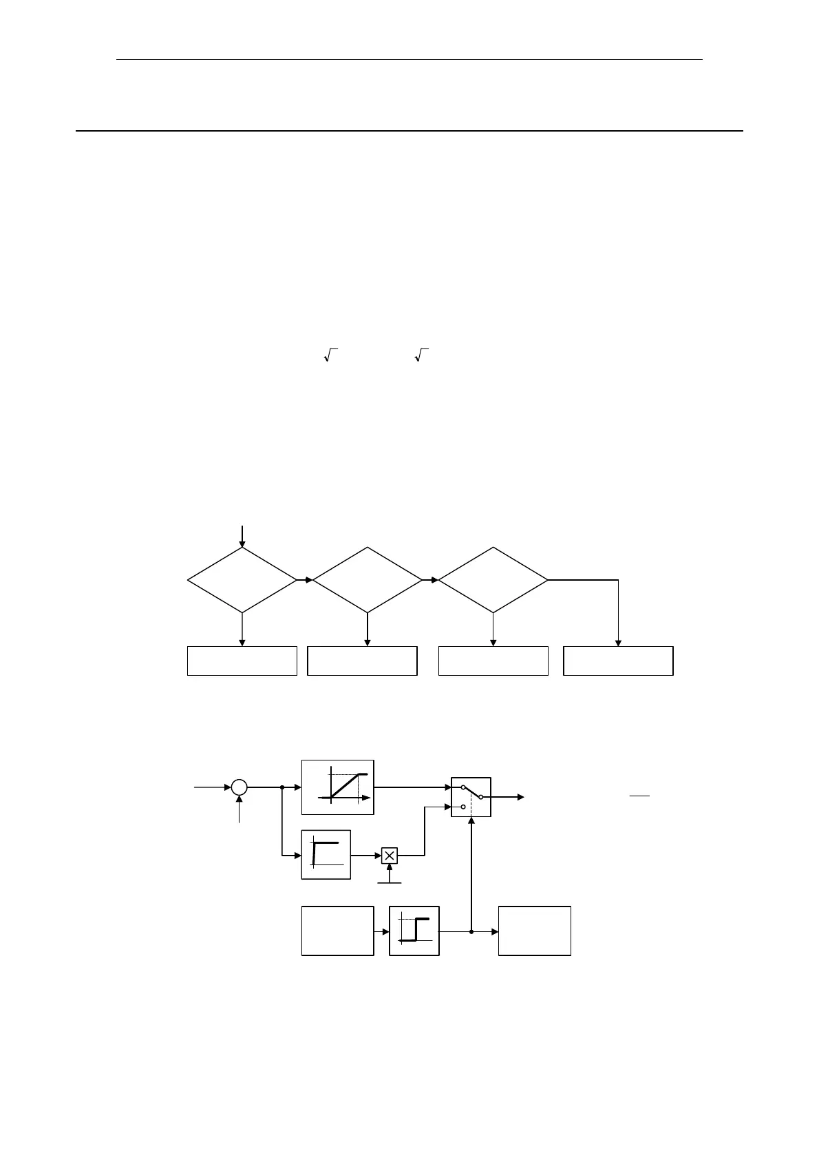
Dynamic braking switch-on level
DC braking
P1233 > 0
?
yes
no
DC braking
enabled
Compound
braking
P1236 > 0
?
Compound braking
enabled
Dynamic
braking
P1237 > 0
?
Dynamic braking
enabled
disabled
no no
yes yes
t
Chopper, ON
t
100
x
⋅=
Chopper
V
DC, act
–
V
DC, Chopper
100 %
V
∆V
0
1
1
0
x
Alarm
A0535
Duty cycle
monitoring
0
1
p1237
∆V = 17.0 V for 380 - 480 V
 Loading...


