Technology Functions
Function diagrams
2-347
© Siemens AG 2007 All Rights Reserved
SINAMICS G120 Control Units CU240S, Edition 05/2007
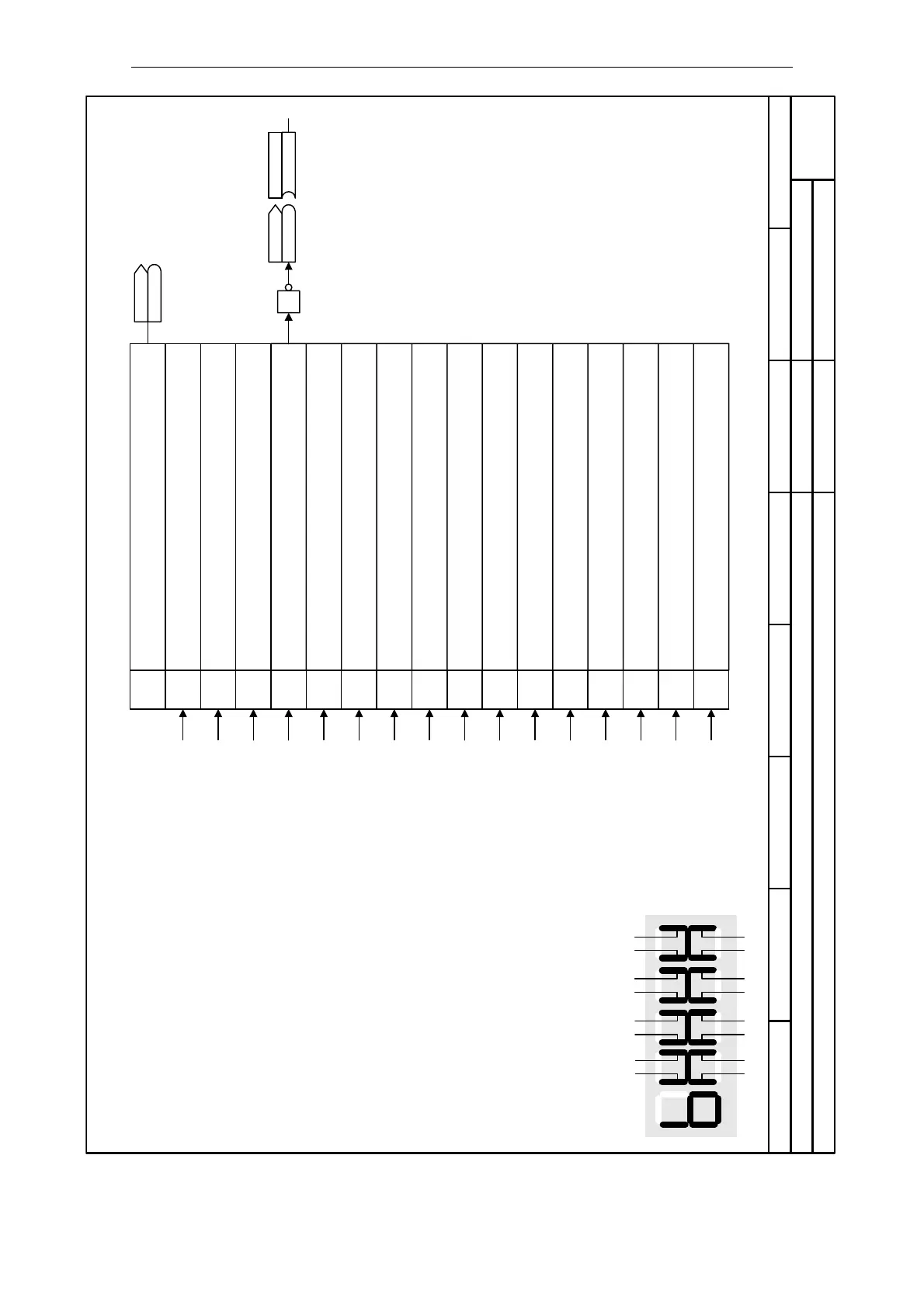
Fig. 2-25 4170 – Status word 1 (r0052)
- 4170 -
Function diagram
87654321
4170_ZSW1.vsd
Technology Functions
SINAMICS G120
02.04.2007 V3.0
Status word 1 (r0052)
1
2
3
4
5
6
7
8
9
10
11
12
13
14
15
0
1
(x.x)
P0731..P0733
r0052.03
r0052
1 0 3 25 4 7 6
9 8
11 10 13 12 15 14
Segment Bit
Segment Bit
Seven-segment display
Act StatWd1
r0052
r0052
Parameter r0052
1 = Drive ready
0 = Drive not ready
1 = Drive ready to run (DC link loaded, pulses disabled)
0 = Drive not ready to run
1 = Drive running (voltage at output terminals)
0 = Pulses disabled
1 = Drive fault active (pulses disabled)
0 = No fault
0 = OFF2 active
1 = No OFF2
0 = OFF3 active
1 = No OFF3
1 = ON inhibit active
0 = No On inhibit (possible to switch on)
1 = Drive warning active
0 = No warning
0 = Deviation setpoint / act. value
1 = No deviation setpoint / act. Value
1 = PZD control (always 1)
1 = f_act >= P1082 (f_max)
0 = < P1082 (f_max)
0 = Warning: Motor current limit
1 = Motor current limit not reached
1 = Motor holding brake active
0 = Motor holding brake not active
0 = Motor overload
1 = No Motor overload
1 = Motor runs right
0 = Motor does not run right
0 = Inverter overload
1 = No inverter overload
Sequence control 1)
Sequence control 1)
Sequence control 1)
Sequence control 1)
Sequence control 1)
Sequence control 1)
Sequence control 1)
Sequence control 1)
Alarm processing
Messages
Messages
Messages
Messages
Braking control
Messages
Messages
Signal "Fault active" is inverted if
connected to a digital output which means
that the relay will be in the de-energised
state.
Bit No. Meaning
1)
The sequence control is the internal
control (software) for realizing the
inverter status (r0001)
 Loading...


