Technology Functions
Function diagrams
2-345
© Siemens AG 2007 All Rights Reserved
SINAMICS G120 Control Units CU240S, Edition 05/2007
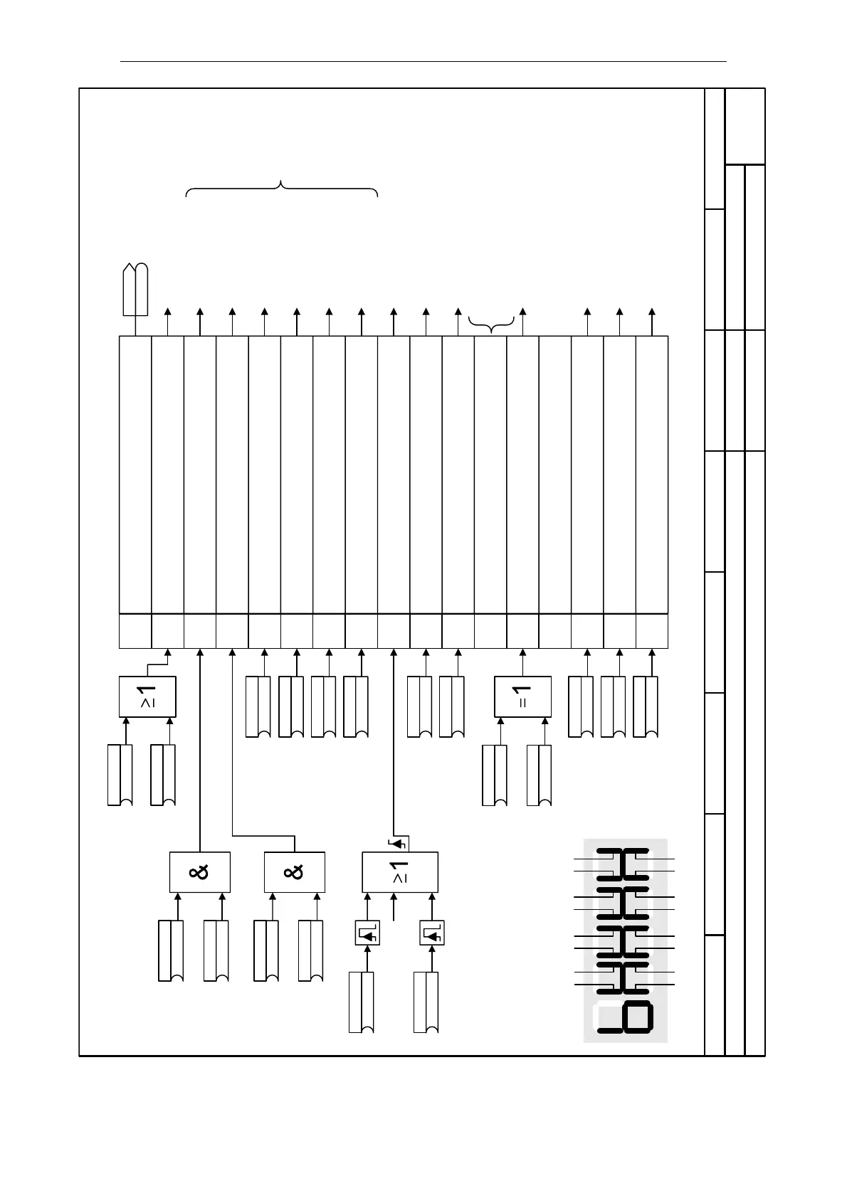
Fig. 2-23 4150 – Control word 1 (r0054)
- 4150 -
Function diagram
87654321
4150_STW1.vsd
Technology Functions
SINAMICS G120
02.04.2007 V3.0
Control word 1 (r0054)
1)
1 0 3 2 5 4 7 6
9 8
11 10 13 12 15 14
1
2
3
4
5
6
7
8
9
10
11
12
13
14
15
0
The sequence control is the internal
control (software) for realizing the
inverter status (r0001)
Sequence control 1)
Setpoint channel
Setpoint channel
Setpoint channel
Setpoint channel
Sequence control 1)
Setpoint channel
Sequence control 1)
Sequence control 1)
Setpoint channel
Setpoint channel
Setpoint channel
Sequence control 1)
Sequence control 1)
Setpoint channel
Braking control
Sequence control 1)
Braking control
Sequence control 1)
Setpoint channel
Braking control
All bits = 1 -->
drive runs
Note:This bit must be set in the first PZD word of the
telegram received from serial interfaces,
so that the converter will accept the process data as
being valid (compare USS, PROFIBUS, etc.)
BOP/AOP via "Fn"
Segment Bit
Segment Bit
Seven-segment display
Bit No. Meaning
0 = ON/OFF1, Shutdown via ramp, followed by pulse disable
1 = ON, operating condition (edge-controlled)
0 = OFF2: Electrical stop, pulse disable, motor coasts down
1 = Operating condition
0 = OFF3: Fast stop
1 = Operating condition
1 = Pulse enable
0 = Pulse disable
1 = RFG enable
0 = Set RFG to 0
1 = RFG start
0 = Stop RFG
1 = RFG setpoint enable
0 = Setpoint disable
0 = No
1 = Fault acknowledge
0 = NO
1 = JOG right
0 = NO
1 = JOG left
1 = Control from PLC
0 = No control from PLC
1 = Reverse (setpoint inversion)
0 = Revers disabled
reserved
0 = NO
1 = Motor potentiometer MOP up
0 = NO
1 = Motor potentiometer MOP down
0 = NO
1 = CDS Bit 0 (local/remote)
(722.0)
ON/OFF1
P0840.CDS
(0)
BI:ON reverse/OFF1
P0842.CDS
(1)
1. OFF2
P0844.CDS
(19.1)
2. OFF2
P0845.CDS
(1)
1. OFF3
P0848.CDS
(1)
2. OFF3
P0849.CDS
(722.2)
1. Faults ackn
P2103.CDS
(0)
2. Faults ackn
P2104.CDS
(1)
Pulse enable P0852.CDS
(1)
RFG enable
P1140.CDS
(1)
RFG start
P1141.CDS
(1)
RFG enable setp
P1142.CDS
(0)
Enable JOG -> P1055.CDS
(0)
Enable JOG <-
P1056.CDS
(19.13)
Enable MOP(UP)
P1035.CDS
(19.14)
Enable MOP(DWN)
P1036.CDS
(0)
CDS bit 0
P0810
(0)
BI:ON reverse/OFF1
P0842.CDS
(722.1)
Reverse
P1113.CDS
Act CtrlWd1
r0054
r0054
Parameter r0054
 Loading...


