External Interfaces
Function diagrams
2-331
© Siemens AG 2007 All Rights Reserved
SINAMICS G120 Control Units CU240S, Edition 05/2007
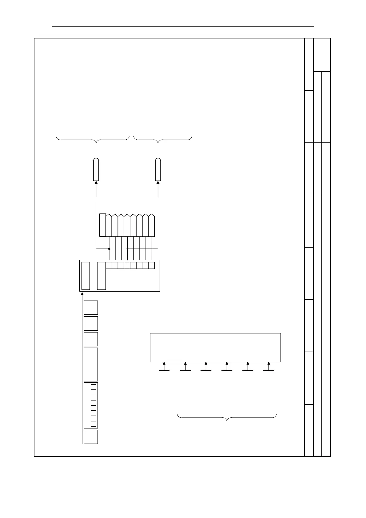
Fig. 2-11 2600 – USS on RS485, Receiving
- 2600 -
Function diagram
87654321
2600_USSon485.vsd
External Interfaces
SINAMICS G120
02.04.2007 V3.0
USS on RS485, Receiving
PKW
PZD
1
[0]
r2018
[1]
[2]
[3]
2
3
4
5
6
7
0
[4]
[5]
[6]
[7]
STXLGEADRBCC
PZD
PKW
07 6 5 4 3 2 1
RxD
Bit3 = 1
CtrlWd 1 <- COM
r2036
CtrlWd2 <- COM
r2037
Change par. via
- ... -
P0927 (1111 bin)
USS baudrate
4 ... 12
P2010 [2] (8)
USS address
0 ... 31
P2011 [2] (0)
USS PZD length
0 ... 8
P2012 [2] (2)
USS PKW length
0 ... 127
P2013 [2] (127)
USS telegram T_off
0 ... 65535 [ms]
P2014 [2] (0)
USS
configuration
Receive telegram Receive
All parameters:
Index = 0
=> RS485
Note:
Bit 10 must be set in the first PZD word of the
telegram received via USS so that the converter
will accept the process data as
being valid. For this reason, the control word 1
must be transferred to the converter in the first
PZD word.
Bit00 ON/OFF1
Bit01 OFF2: Electrical stop
Bit02 OFF3: Fast stop
Bit03 Pulse enable
Bit04 RFG enable
Bit05 RFG start
Bit06 Setpoint enable
Bit07 Fault acknowledge
Bit08 JOG right
Bit09 JOG left
Bit10 Control from PLC
Bit11 Reverse (setpoint inversion)
Bit13 Motor potentiometer MOP up
Bit14 Motor potentiometer MOP down
Bit15 CDS Bit 0 (Local/Remote)
Bit00 Fixed frequency Bit 0
Bit01 Fixed frequency Bit 1
Bit02 Fixed frequency Bit 2
Bit03 Fixed frequency Bit 3
Bit04 Drive data set (DDS) Bit 0
Bit05 Drive data set (DDS) Bit 1
Bit08 PID enabled
Bit09 DC brake enabled
Bit11 Droop
Bit12 Torque control
Bit13 External fault 1
Bit15 Command data set (CDS) Bit 1
 Loading...


