"4JWBSJBOU
*0WBSJBOU
7146PQUJPOBM
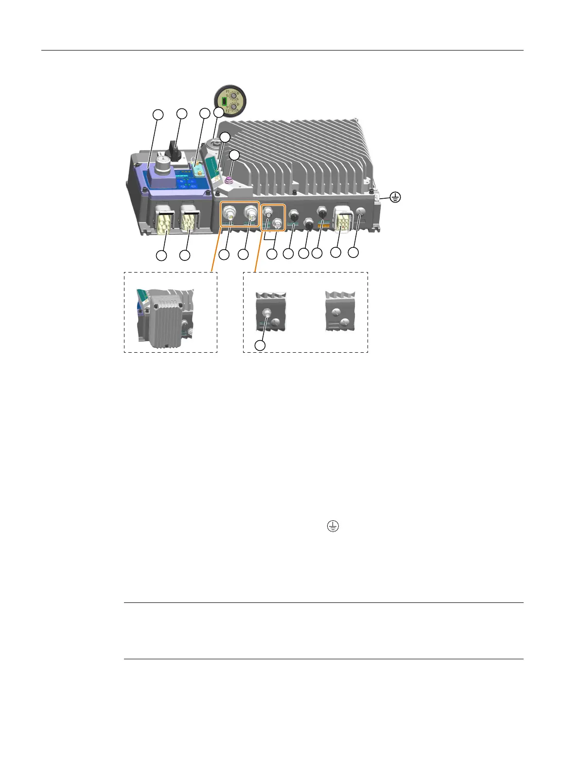
① Line supply interface (IN) - X1 ⑩ External braking resistor interface - X4
② Line supply interface (OUT) - X3 ⑪ Fan unit connector
2)
③ 24VDC power supply interface (IN) - X01
4)
⑫ Status LED
④ 24 V DC power supply interface (OUT) - X02
4)
⑬ Commissioning interface, including a mini-
USB interface and two electromechanical po‐
tentiometers P1/P2
⑤ PROFINET communication - X150 P1 and P2
(for PROFINET variant only)
⑭ Memory card interface
⑥ Digital inputs DI 0 and DI 1 - X07 ⑮ Repair switch
1)3)
⑦ Digital inputs DI 2 and DI 3 - X08 ⑯ Local/remote control panel
1)3)
⑧ Bidirectional digital inputs/outputs DIO 24
and DIO 25 - X05
⑰ AS-i communication and auxiliary power -
X03 (for AS-i variant only)
⑨ Motor power interface - X2
1)
Protective earth on the converter housing
1)
Available on the wall-mounted converter only.
2)
The fan connector is designed for use in the wall-mounted converter FSB (4 kW)/FSC.
3)
Optionally available on the wall-mounted converter only.
4)
Not available on the AS-i variant.
Note
The electromechanical potentiometers, the repair switch, and the local/remote control panel on
the converter do not provide protection against unauthorized access. You must take appropriate
measures to protect the converter against unauthorized operation or changes to the settings.
Wiring
5.7Overview of the converter interfaces
SINAMICS G115D Wall Mounted distributed drive
62 Operating Instructions, 07/2023, FW V4.7 SP14, A5E52808211A AA

 Loading...


