120 Chapter 9
Communication with External Equipment (Using the I/O Ports)
Using the I/O Ports
Using the I/O Ports
8-bit I/O port
The 8-bit I/O port of the 4294A consists of the following TTL signal lines.
• OUT0 to OUT7 (8-bit output)
• IN0 to IN3 (4-bit input)
• GND (ground)
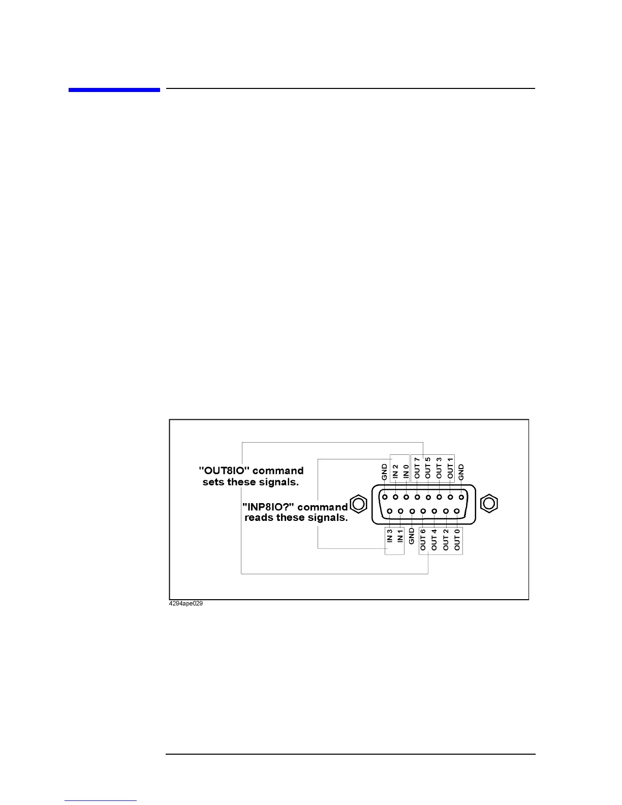
Definition of the I/O pins
Each signal of the 8-bit I/O port is described below. Figure 9-1 shows the pin assignment
diagram.
OUT 0 to 7 Signal lines that can be set freely from the controller. Use these lines to
send signals from the controller to external equipment. Once signals
are outputted form the controller, the states of these signal lines are not
changed until the controller outputs the next signals (latched).
IN 0 to 3 Signal lines that can be read out from the controller. Use these lines to
send signals from external equipment to the controller.
GND (3 pins) Ground line.
Figure 9-1 8-bit I/O port

 Loading...


