122 Chapter 9
Communication with External Equipment (Using the I/O Ports)
Using the I/O Ports
24-bit I/O port
The 24-bit I/O port of the 4294A consists of 4 independent data input/output parallel ports,
several control signal lines, and a power line. All the signals provide TTL level.
The data input/output port consists of 2 sets of 8-bit output ports and 2 sets of 4-bit
bi-directional ports. You can use these ports as up to a 24-bit output port or up to a 8-bit
input port, by using them concurrently.
The input/output signals are preset to negative logic, but you can change the setting to
positive logic. The control signal lines include the measurement completion output or
control signal outputs for handshaking.
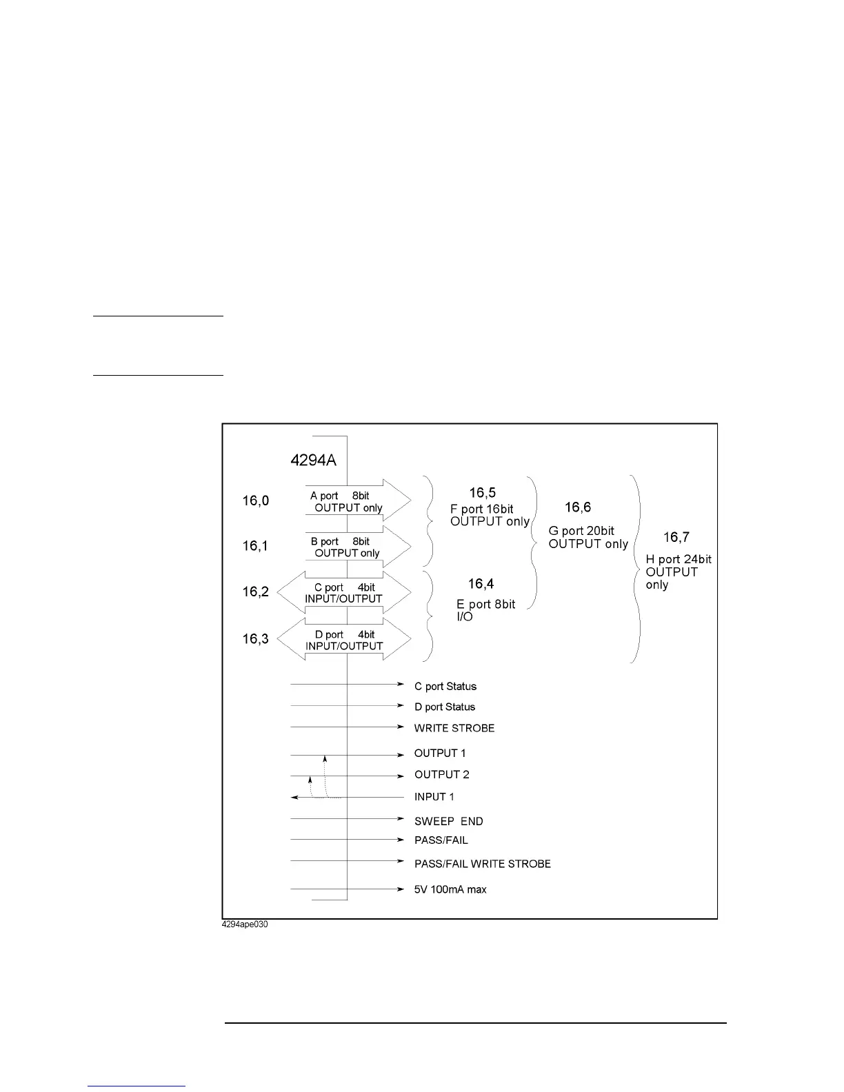
Figure 9-2 shows the overview diagram of the
input/output ports and the control signal lines.
NOTE If a device cannot be connected directly to the 24-bit I/O interface connector on the rear
panel of the 4294A, a 36-pin cable (part number: 04278-61650) is available. By connecting
this cable, the distance from the 24-bit I/O interface can be extended by 1 m.
Figure 9-2 Overview diagram of the 24-bit I/O port

 Loading...


