124 Chapter 9
Communication with External Equipment (Using the I/O Ports)
Using the I/O Ports
When this input falls (a pulse is inputted), the OUTPUT1 output and the OUTPUT2 output
go LOW or HIGH. The delay between the fall of the input and the state transition of both
outputs is 200 ns (typical). To select LOW or HIGH of both outputs, use the GPIB
command. The pulse width of a signal inputted to INPUT1 must be 1 μs or more.
OUTPUT1 output, OUTPUT2 output
These signal lines are latched output terminals that can be set to LOW or HIGH by a rise of
the INPUT1 input or the GPIB command.
PASS/FAIL output
Outputs HIGH (for positive logic) or LOW (for negative logic) when the limit test result is
PASS; LOW (for positive logic) or HIGH (for negative logic) when FAIL. This is available
only when the limit test function is on.
Write strobe output for PASS/FAIL output
When the limit test result is outputted to the PASS/FAIL output line, a negative pulse is
outputted to this write strobe output. The outputted pulse width is 10 μs (typical). This
output signal notifies external equipment that the limit test result is outputted to the
PASS/FAIL output.
SWEEP END output
Outputs a negative pulse when the 4294A completes a sweep. The outputted pulse width is
20 μs (typical). If the continuous sweep trigger is sent, a pulse is generated each time a
sweep is completed.
+5V output
Provides a +5V output for external equipment. The maximum supply current is 100 mA.
This line has no fuse, but, if over-current flows, the protection circuit of the 4294A
operates and the main power to the 4294A is automatically cut off. When the cause of
over-current is removed, the power to the 4294A is restored, but the instrument states are
reset to the power-on states.
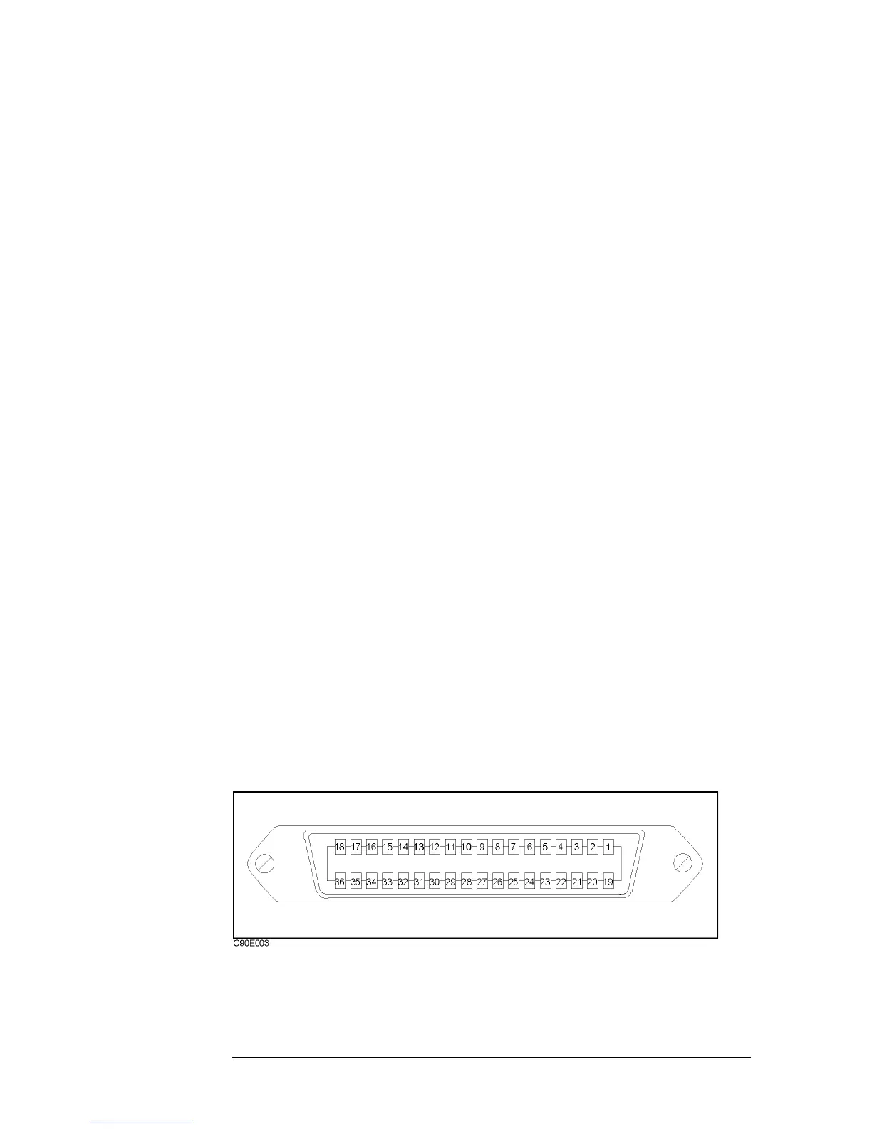
Definition of I/O pins
Figure 9-4 shows pin numbers, and Table 9-1 shows the relationship between signal lines
and pin numbers.
Figure 9-4 Pin numbers of the 24-bit I/O port connector

 Loading...


