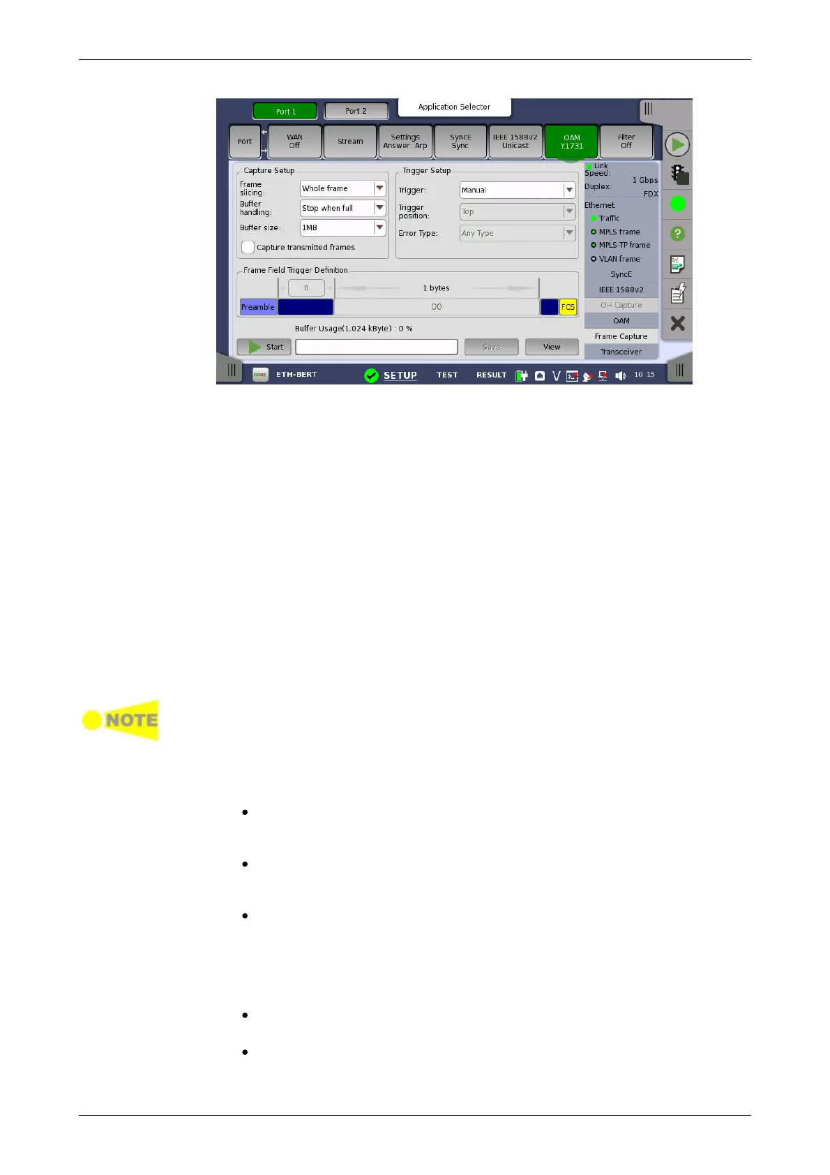
Capture Setup
Trigger Setup
This screen allows you to set up and execute capture of transmitted frames.
Frame slicing
Use the Frame slicing drop-down menu to specify which part of the frame
will be captured. The available options are: Whole frame, Top 64 Byte,
Top 128 Byte.
Buffer handling
Use the Buffer handling drop-down menu to choose either Stop when full
or Overwrite.
Buffer size
Use the Buffer size drop-down menu to specify the size of the buffer. The
specified size will be reflected in the Buffer Usage indicator at the bottom of
the screen.
Capture transmitted frames
Select the check box if capturing the transmitted frames.
Clear the check box to capture the incoming frames.
During the 10 Gbit/s rate state, transmitted streams the traffic generator sends
can't be captured.
Transmitted protocol frames can be captured. 'Protocol frames' are the frames
which used for information such as ARP, SyncE, IEEE1588v2, OAM.
This is the same for 10GbE over OTN (OTU2e - 10GbE mapping).
Trigger
Manual
This is the default setting, which captures all frames. All other trigger
setup parameters are disabled.
Error
Frame capture starts when the error specified by Error Type drop-
down menu has occurred.
Field match
Frame capture starts if the field in transmitted frame matches to one
defined by Frame Field Trigger Definition.
Trigger position
Select the position of a trigger frame in the captured data.
Top
The trigger frame will be located at top of the captured data.
Middle
The trigger frame will be located at center of the captured data.