Module Present
Transceiver
Information
Power monitor
Alarms/Errors/
Others
Green indicates that an optical transceiver is currently mounted.
Select the information from pull down menu.
Wavelength and bit rate shows the nominal wavelength and bit rate.
Compliance shows the available standards.
Vendor information shows the data stored in the optical transceiver.
The optical power read out from the transceiver is displayed.
The transmitting optical power is displayed in left column. The received
optical power is displayed in right column.
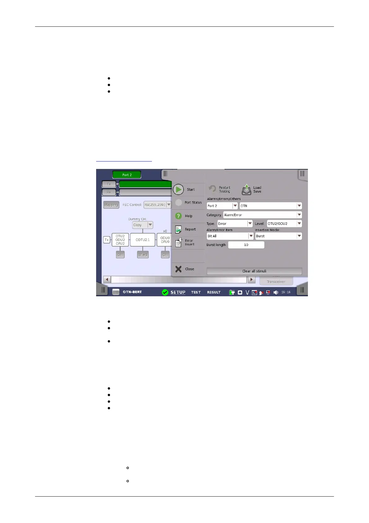
7.1.4 Error/Alarm Insertion
This section describes the errors or alarms insertion for the OTN layer on the
Application toolbar.
Select the port to insert errors, and the stimuli type. The settings items vary
depending on the selected stimulus type.
OTN: Inserts errors or alarms related the OTN overhead or FEC.
OTN frequency: Adds the frequency offset to the OTU bit rate and
Payload bit rate.
OTN justification: Inserts positive or negative justification bytes of AMP
(asynchronous mapping procedure).
7.1.4.1 OTN
If selecting OTN, the Category drop down menu appears.
Alarms/Errors: Inserts errors or alarms related the OTN overhead.
GMP: Inserts errors to the general mapping procedure parameter.
GFP: Inserts errors to the generic framing procedure parameter.
FEC Test: Inserts errors to the forward error correction bytes in the OTU
frame.
Alarms/Errors
1. Select Alarm or Error using Type drop down menu. If selecting Off,
Errors and Alarms are not inserted.
2. Select the Level.
3. Select the Alarm/Error Item.
4. Select the Insertion Mode.
Single: Inserts an error or an alarm if you touch the Error Insert
icon.
Burst: Inserts errors or alarms in counts you have specified if you