Clock
Configuration
Transceiver
Follows
Frame Setup
side.
Use the drop-down menu to select the clock source. This is fixed to
Received when Transmission is set to Through or OH overwrite.
Timing Source
Internal: Internal clock of the module
External: The clock input to the connector
GPS: The clock provided from the external GPS sensor
Received: The clock generated from the received signal
When External, GPS or Received is set, the right hand lamp indicates
whether clock is detected or not.
Displays the Transceiver information when Optical Transmitter is selected.
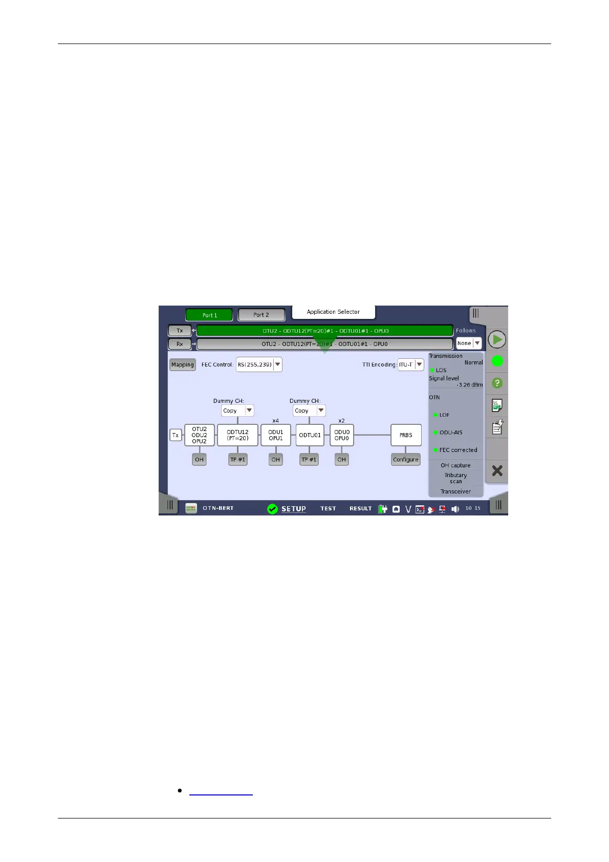
7.1.1.2 OTUk Frame Setup
Touching the navigation area button which represents the transmitter's OTN
layer will launch the screen shown below.
This screen allows you to configure OTUk frame of the currently selected
transmitter. It can also be used to inspect the current status of the selected
port in a separated screen.
The configuration options available in the setup area of the screen are
described below. The status information is described in a separate section.
To setting up the OTU frame, touch Mapping button at first. Then select the
relevant values for the various containers in the structure shown in the setup
area, either by opening a drop-down menu or by touching a button to launch
an editor dialog.
Note that the changes you make will be reflected in the text displayed in the
OTUk button in the navigation area.
To make the Port 2 transmitter follow the Port 1 transmitter (i.e. copy its
settings), touch the right-most button in the navigation area and select the
Tx1 in the drop-down menu. The Port 2 settings continue to follow the Port 1
transmitter change. The default setting is None. Note that the Port 1
transmitter cannot follow the Port 2 transmitter.
Mapping
Touch the Mapping button and use the launched dialog box to define the
OTUk frame mapping. The following settings are available:
Output Signal