Connector
Drop and insert
Timing Source
Follows
2. Touch STM-xx, STS-xx, or OC-xx button in the navigation area.
3. Use drop down menu at right bottom to switch SDH or SONET. Selecting
the SDH displays PDH Tx on Tx screen. Selecting the SONET displays
DSn Tx on Tx screen.
4. Touch Tx button in the navigation area.
5. Select PDH Tx or DSn Tx check box.
6. Clear SDH Tx or SONET Tx check box.
7. Touch E1 radio button. Touching Off radio button disables the
transmitter.
This screen allows you to make the physical setup of the PDH transmitter in
E1 mode. It can also be used to inspect the current status of the selected
port.
The configuration options available in the setup area of the screen are
described below. The status information is described in a separate section.
Select the type of the input/output connectors of the instrument. Choose
Unbalanced to link to the corresponding unbalanced connector, or choose
Balanced to link to the corresponding balanced connector. A balanced
output goes to the RJ48 connector.
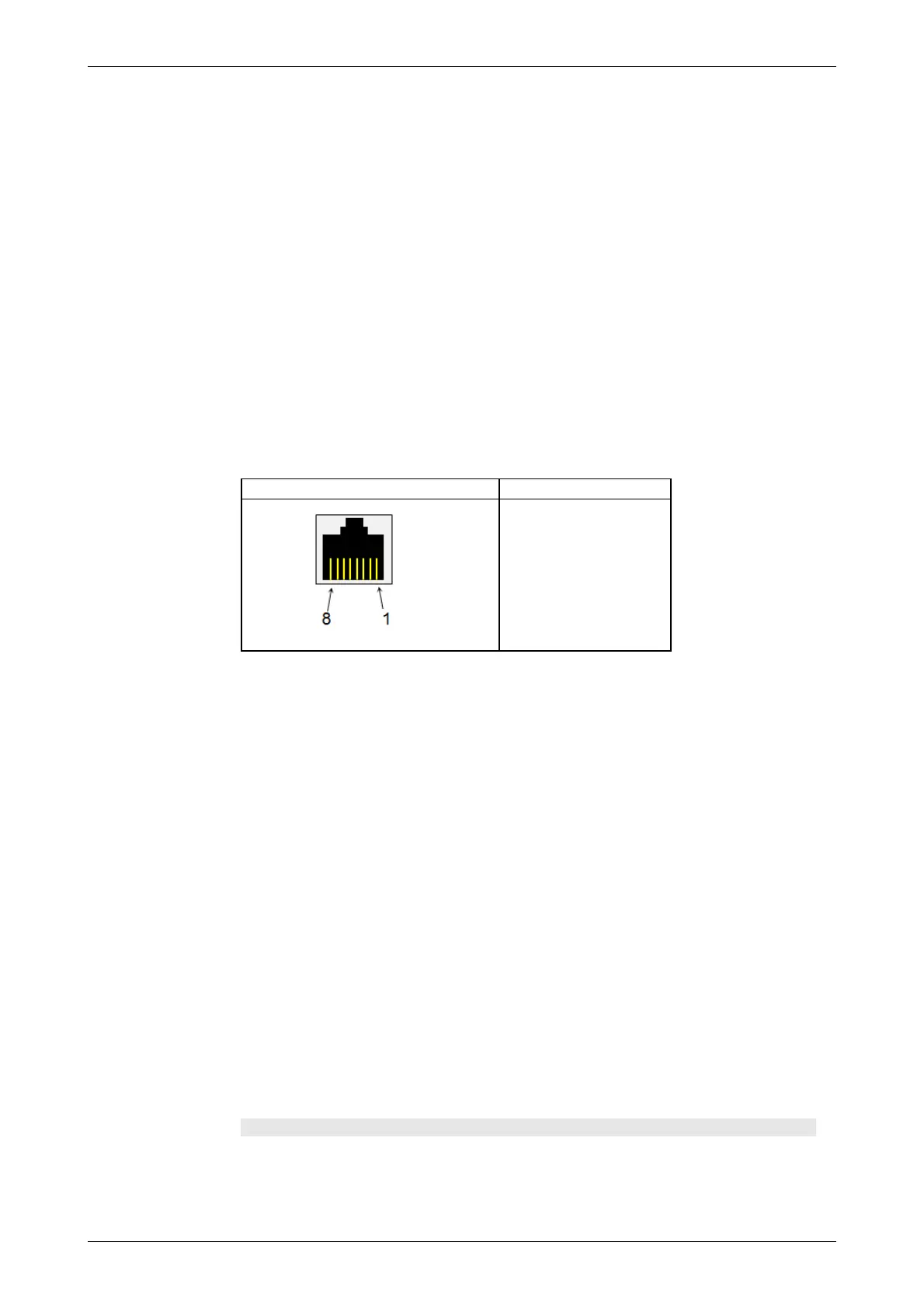
Pin assignment of E1 Balanced Connectors
RJ-48 Pin Signal
1 RX, Ring
2 RX, Tip
3 Ground
4 TX, Ring
5 TX, Tip
6 Ground
7 No connect
8 No connect
Be sure to confirm the cable type. For E1 cable, there are the straight cable
and the cross cable.
Select the source for the transmitter.
On: transmits the received data which the data generated in the Network
Master has added.
Off: transmits the data generated in the Network Master.
Select the clock source.
Internal: Internal clock of the module
External: The clock provided from the Ext Clock connector
Received: The clock generated from the received signal
When External or Received is set, the right hand lamp indicates whether
clock is detected or not.
5.3.1.2 E1 Signal Setup
Touching the navigation area button which represents the transmitter's E1
layer will display the screen.
To make the Port 2 transmitter follow the Port 1 transmitter (i.e. copy its
settings) when using Port 1 and Port 2, touch the drop-down menu in the
navigation area and select the Tx1. The Port 2 settings continue to follow the
Port 1 transmitter change. The default setting is None. Note that the Port 1
transmitter cannot follow the Port 2 transmitter.
Frame tab page
The Frame tab page contains the following parameters: