AP Servo Installation, Configuration, and Calibration
SkyView System Installation Guide - Revision AA 10-7
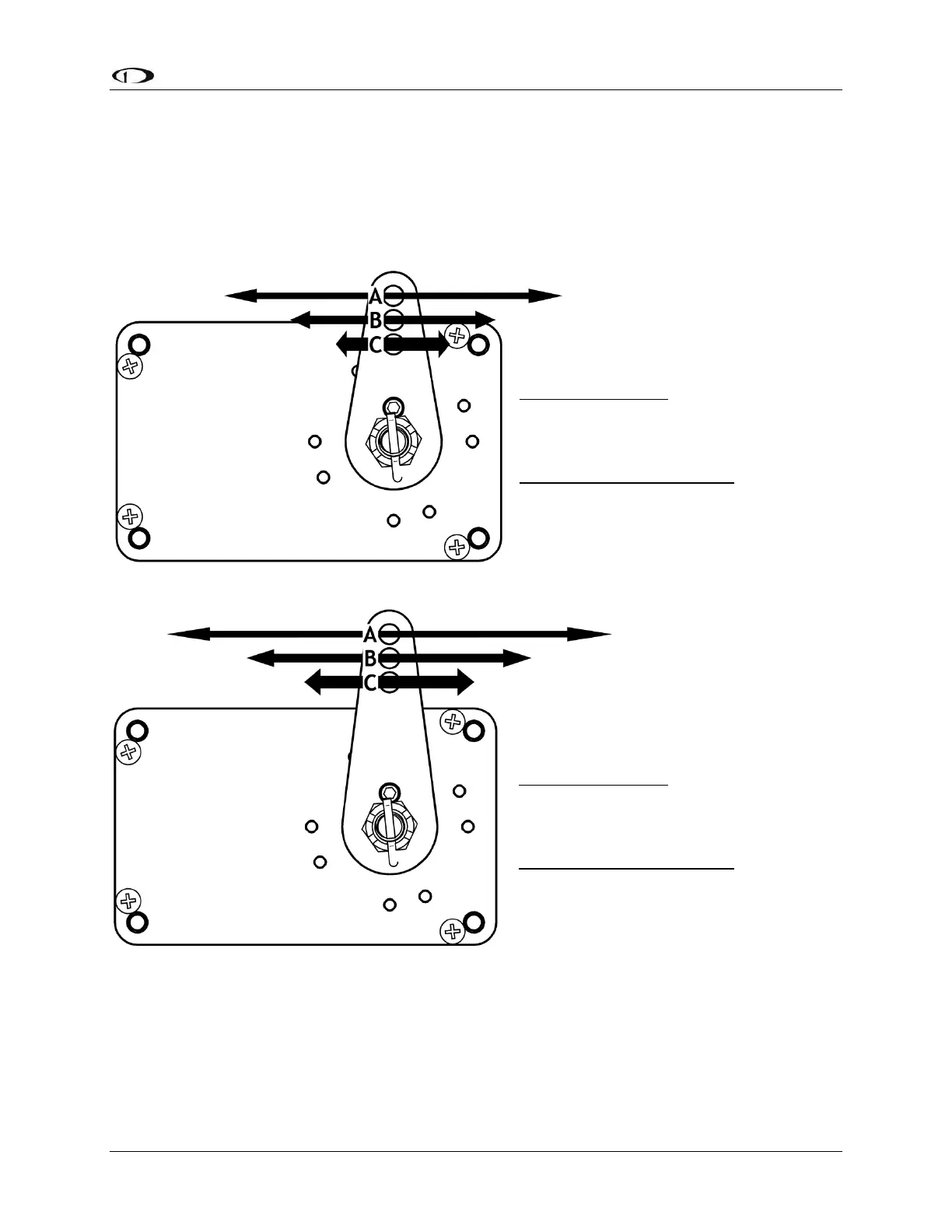
Linkage Mount Position Force and Travel
The two diagrams below illustrate the maximum travel and force available at each linkage
mounting point. As can be seen, the closer you mount the linkage to the shaft, the more force
the servo can deliver. However, this also means the travel of the arm is shorter. Again, ensure
that the servo arm is nowhere near going over-center throughout the entire range of the control
system.
The maximum linear travel specifications called out above denote the distance traveled by the
location on the arm such that it is 60° from center at maximum distance in either direction (e.g.,
the A hole on the standard servo arm can linearly travel 1.3” (33mm) from center in either
direction).
Standard Arm
Max Linear Travel
A: 2.6” (66mm), B: 2.2”
(55.9mm), C: 1.8” (45.7mm)
Max Force @ 100% Torque
SV32 - A: 24lb B: 29lb C: 36lb
SV42 - A: 36lb, B: 44lb, C: 55lb
SV52 - A: 48lb, B: 58lb, C: 72lb
Figure 109 – Servo Arm Throw/Torque – Standard Arm
Long Arm
Max Linear Travel
A: 3.4” (86.4mm), B: 3.0”
(76.2mm), C: 2.6” (66.1mm)
Max Force @ 100% Torque
SV32L - A: 18lb, B: 20lb, C: 24lb
SV42L - A: 27lb, B: 31lb, C: 36lb
SV52L - A: 36lb, B: 41lb, C: 48lb
Figure 110 – Servo Arm Throw / Torque – Long Arm