AP Servo Installation, Configuration, and Calibration
10-8 SkyView System Installation Guide - Revision AA
During installation, the linkage hardware must be connected to the servo arm such that the
servo can actuate the connected control surface while approaching, but not exceeding the
called out maximum linear travel specification. If too much slippage occurs during servo flight
testing, it may be necessary to use a stronger servo.
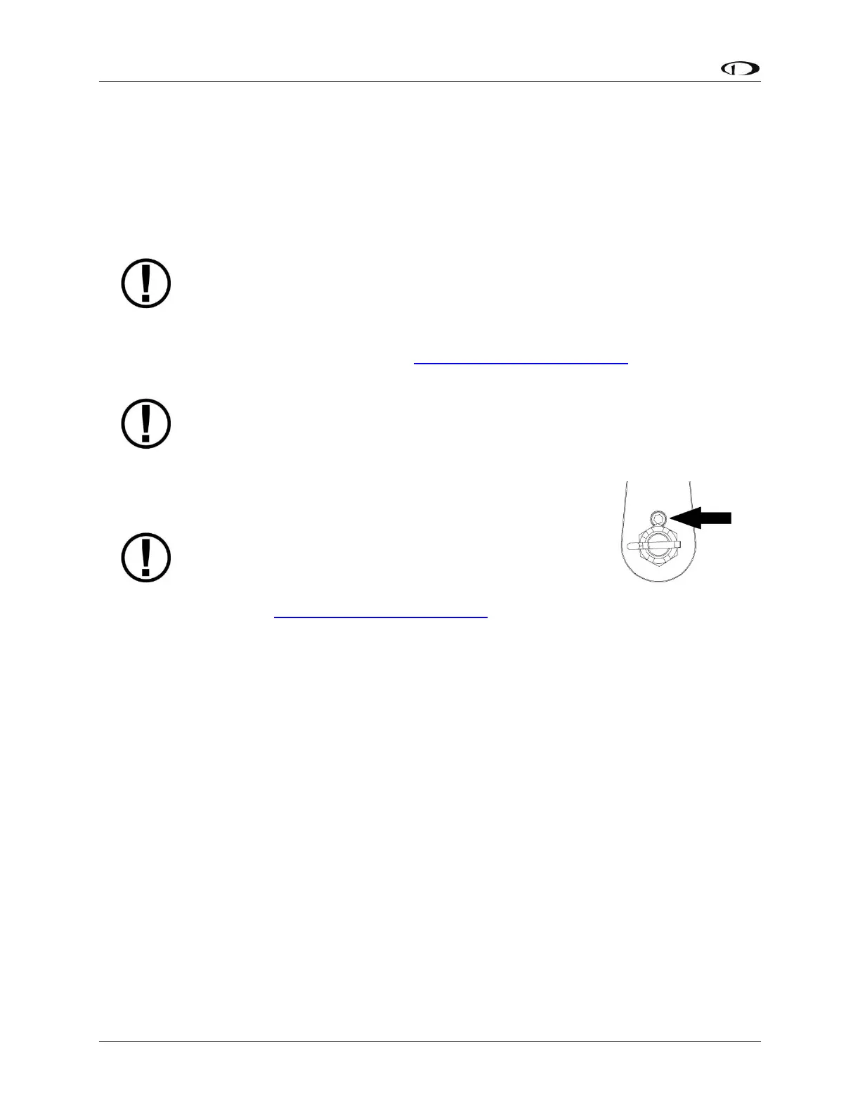
Each Dynon Avionics servo includes a precision-machined brass shear screw that
pins the servo arm to the servo arm attachment, providing an ultimate manual
override. Servo shear screws will break at the application of 100 inch-pounds of
torque, at which point the servo arm will travel freely. If the brass shear screw is
broken during autopilot installation or usage, do not replace it with a standard
screw– contact Dynon Avionics Technical Support (contact information at the
beginning of this manual) for a replacement shear screw. Instruction for replacing
the shear screw can be found at http://docs.dynonavionics.com.
A broken shear screw indicates an abnormal condition in the installation and/or
operation of the autopilot and servo, much as a blown fuse or a tripped circuit
breaker indicates a problem in the electrical system. Shear screws should be
replaced with proper parts only after any problems are corrected.
The servo shear screw should NEVER be removed
or adjusted in the normal process of installing an
autopilot servo. Instructions for both replacing a
broken shear screw and instructions for changing
or replacing the servo arm / capstan assembly can
be found at http://docs.dynonavionics.com.
There will be a variety of methods used to install the other end of this control linkage to the
existing mechanicals of the aircraft. Some systems will use a hole drilled into the bell crank as
the point where the servo push rod/rod end combination interfaces with the controls. Others
will use an attachment to existing linkage. Others may attach directly to the control stick itself.
It is up to the installer to decide which method is best in terms of safety and AP functionality.
Installers should always keep in mind the range of motion of the servo. Total servo arm travel
needs to be limited to prevent an OVER CENTER condition (see caution note above), while still
preserving the control surfaces’ full range of motion. Carefully consider the prevention of an
over center condition when selecting the mounting location and linkage attachment point for
any servo installation. The built-in control stops of the aircraft will limit the servo arm travel
when installed correctly. Again, Dynon Avionics strongly recommends that the included Range
of Motion Limiting Bracket be installed in order to absolutely prevent the possibility of an over
center condition. The Range of Motion Limiting Bracket should not be used as a normal stop;
the aircraft’s built-in stops should always be the primary range limit. The Range of Motion
Limiting Bracket can be installed in different orientations depending on the aircraft geometry.
However, it is important that it constrain the servo arm such that is unable to travel over center
in either direction. An example of how the Range of Motion Limiting Bracket can be installed is