SkyView Display Installation and Configuration
SkyView System Installation Guide - Revision AA 4-23
3. Configure the serial port (under SETUP MENU > SYSTEM SETUP > SERIAL PORT SETUP)
according to the device’s documentation.
4. When serial port configuration is complete, perform a final check by doing the following:
a. Power down all displays except #1. Verify all serial port devices are working -
transponder, GPS, radios, etc.
b. Power down all displays except #2. Verify all serial port devices are working -
transponder, GPS, radios, etc.
c. Power down all displays except #3. Verify all serial port devices are working -
transponder, GPS, radios, etc.
A SkyView Display serial port can be configured to communicate with one device
on its TX and a different device on its RX, but when doing so, the TX and RX speeds
must be the same.
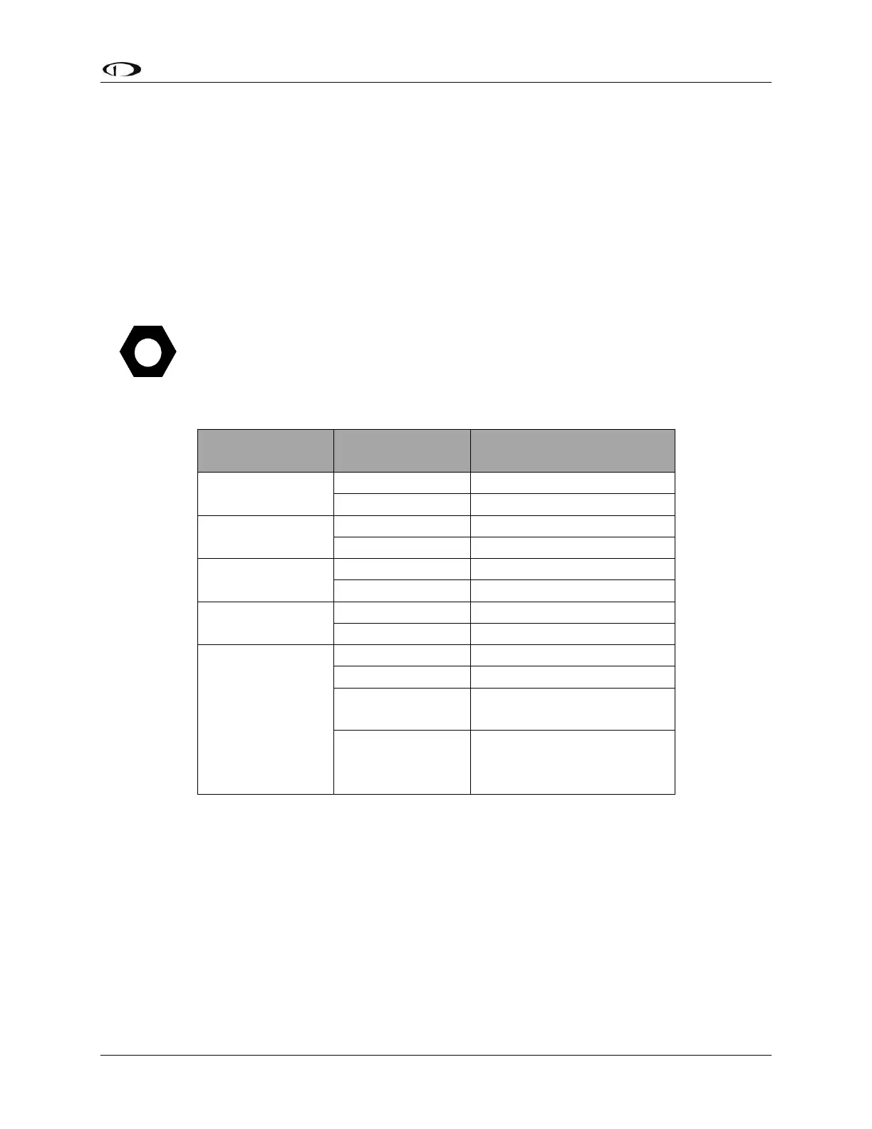
Table 12 contains serial port wire functions and wire harness colors.
SkyView Display Harness
Wire Colors
Yellow with Orange stripe
Yellow with Violet stripe
Table 12 – SkyView Serial Port Connections
Traffic Devices
SkyView has the ability to receive and display aircraft traffic data from:
Dynon Avionics SV-XPNDR-261/262 (from TIS)
Dynon Avionics SV-ADSB-470 (from ADS-B)
Garmin GTX 330 / 330ES (from TIS)
Other devices that output traffic data that emulates “Garmin TIS format” including
Garrecht / AIR Avionics TRX-1500 (set to TIS output), NavWorx ADS-B receiver, and
Zaon XRX (set to “Garmin” output). For such devices, configure the SkyView serial port