2
2. Panel Descriptions
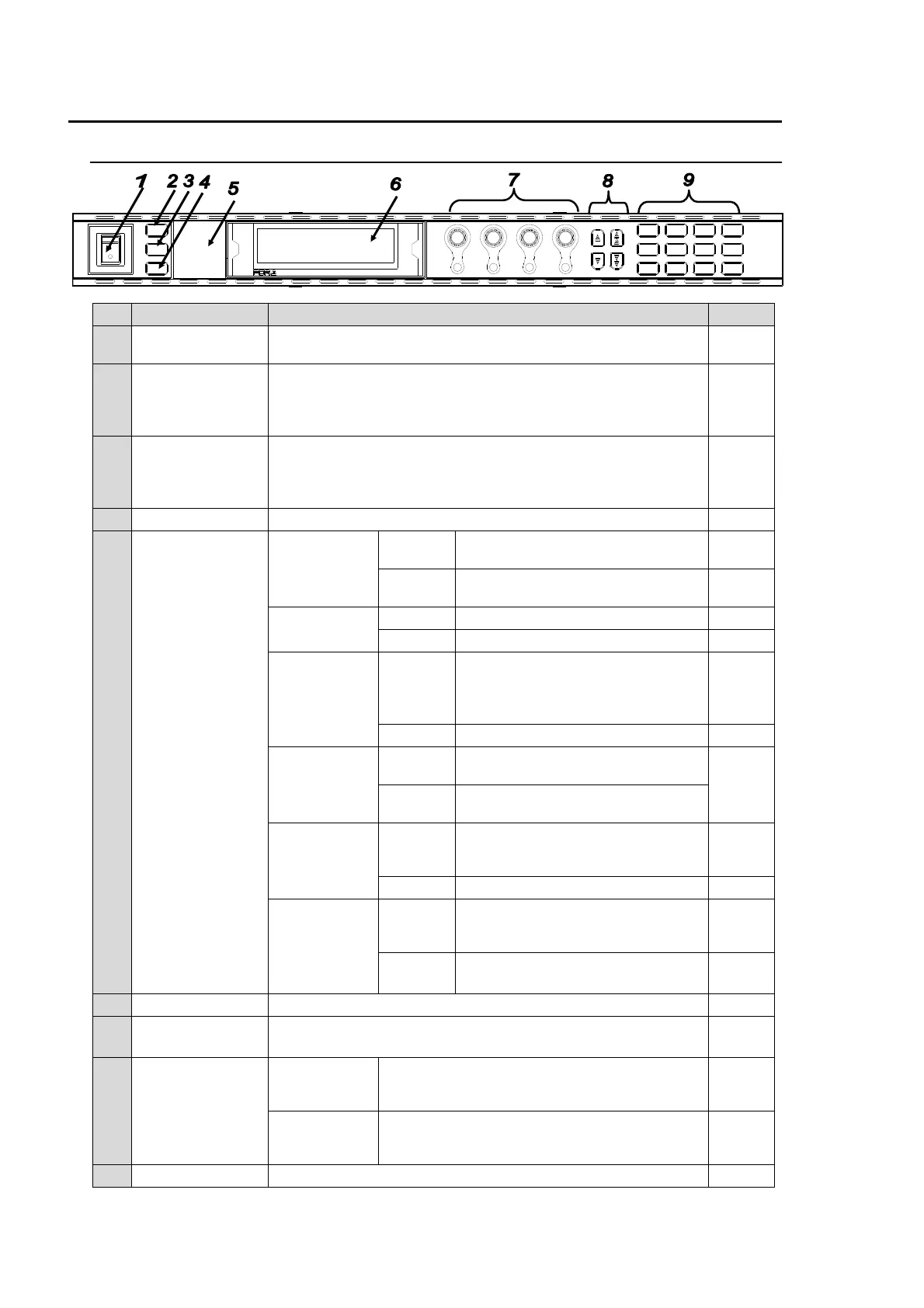
2-1. Front Panel
No Name Description Ref.
1 POWER switch
Used to turn the unit ON / OFF. Pressing the "|" side turns on
the power.
4-1
2 LOCK button
Lit when pressed, and the buttons and controls on the front
panel except this LOCK button are disabled.
To enable the disabled buttons and controls, press and hold
this button down for several seconds.
3 BY-PASS button
Bypasses input signals (video and audio). The input signals
are directly output when the BY-PASS button is pressed (lit).
See the description of No. 2, 4, and 6 of the rear panel for
details.
4 EVENT button Used to save and load events. 8
5 Status indicator
VIDEO IN
Lit green
An input signal is present in the
connector selected in the menu.
5-7
5-13-2
Unlit
An input signal is not present in the
connector selected in the menu.
5-7
5-13-2
AUDIO IN
Lit green An audio signal is present. 6-5
Unlit No audio signal is present. 6-5
GENLOCK
Lit green
A genlock signal input is present.
(Unlit if SYNCHRO is set to
INPUT. See section 5-10-1 FS
MODE SET for details)
5-10-1
5-13-2
Unlit No genlock signal input is present. 5-13-2
REMOTE
Lit green
CONTROL SETTING is set to
REMOTE.
7-1
Unlit
CONTROL SETTING is set to
LOCAL.
DC POWER
*1
Lit red
A power failure has occurred. Turn
the power of the unit OFF, and
contact your supplier.
5-13-1
Unlit Power supply is normal. 5-13-1
FAN ALARM
Lit red
One or more fans have failed. Turn
the power of the unit OFF, and
replace the failed fans if needed.
5-13-1
Unlit All fans are operating normally. 5-13-1
6 Menu display Used to display menus and make operational settings 4-2
7
Controls (F1-F4)
UNITY buttons
Used to change operational settings. Turn and select values.
The Unity buttons return the settings to the default values.
4-2
8 Arrow buttons
Single-arrow
buttons
Used to move between parameters.
(Indicators light up to indicate the accessible
direction.)
4-2
Double-arrow
buttons
Used to move between menus (same as the
menu buttons). (Indicators light up to indicate
the accessible direction.)
4-2
9 Menu buttons Used to select menus. 4-2
*1 The DC POWER indicator functions when the optional FA-95PS is installed.
MASTER
CONV2
OUT SEL
MODE
VIDEO
AUDIO
ANALOG
CONV1
IN SEL
DOWNMIX
STATUS
OTHER
C C
AES AUDIO
CLIP
DELAY
AUDIO SYS
VIDEO SYS
AUDIO O P
VIDEO OP
MAPPING
A V O
PROCESS
SDI AUDIO
F4
UNITYUNITYUNI TYUN ITY
F3
F2
F1
F A - 9 5 0 0
DISPLAY AREA
HD / SD FRAME SYSNCHRONIZER
VIDEO IN
AUDIO IN
GENLOCK
REMOTE
FAN ALARM
DC POWER
BY-PASS
LOCK
EVENT
ON
OFF
POWER
F1
F2
F3
F4