7
3. Connections
This section describes the connections and settings for specific usages. The descriptions on the
settings are based on the factory default. If you are not sure of your current settings, you can reset
the unit to the default setting by selecting DEFAULT in the EVENT LOAD menu described in the
section 8-1 “EVENT LOAD”.
3-1. For HD /SD-SDI Frame Synchronizer Use
Settings that need to be checked:
INSEL is set to SDI1 as described in section 5-7 “VIDEO INPUT SELECT (IN SEL)”.
CONV1 is set to BY-PASS as described in section 5-3-1 “CONV1 U/D MODE”.
SDI1/2 OUT SET is set to CONV1 as described in section 5-8 “VIDEO OUT SELECT (OUT
SEL)”. (To output the same synchronized signal from SDI3 and 4, set SDI3/4 OUT SET to
CONV1.)
Select a sync mode in the SYNCHRO menu as described in section 5-10-1 “FS MODE SET”.
Make sure the SYS FRMT is appropriately set for the input signal as described in section
5-10-1 “FS MODE SET”.
Adjust phase and position to match the reference signal as described in section 5-10-6 “HD
PHASE” if necessary.
NOTE
The SD-SDI input signal in SDI IN1 can also be output from COMPOSITE OUT. To do
so, set COMPOSITE to CONV1 as described in section 5-8 “VIDEO OUT SELECT
(OUT SEL)”. To adjust the signal phase of the output from the COMPOSITE OUT, see
section 5-10-7 “SD PHASE SET”.
The input signal can be selected from the inputs in the SDI IN1, SDI IN2, and
COMPOSITE IN connectors. The input selection can be made by the IN SEL setting
as described in section 5-7 “VIDEO INPUT SELECT (IN SEL)”.
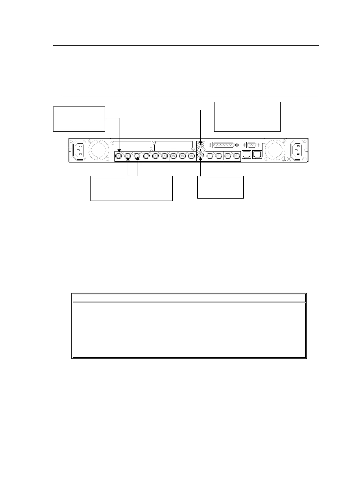
AC100 - 240V 50/60 Hz IN 1
FAN2
SER. NO.
LAN2LAN1
REMOTE
DIGITAL AUDIO IN / OUT
7 / 85 / 63 / 41 / 2
ANALOG AUDIO
GENLOCK IN
COMPOSITE
OUT2OUT1IN
B
OUT4OUT3IN 2OUT2OUT1
SDI
IN1
A
FAN1
AC100 - 240V 50/60 Hz IN2
Terminate at 75
ohm if not used.
Reference signal
(BB or Tri-level sync signal
synchronized with the input
signal.)
Input an HD/SD-
SDI signal to SDI
IN1.
Outputs a signal synchronized
with the reference signal from
SDI OUT1 and 2.