68
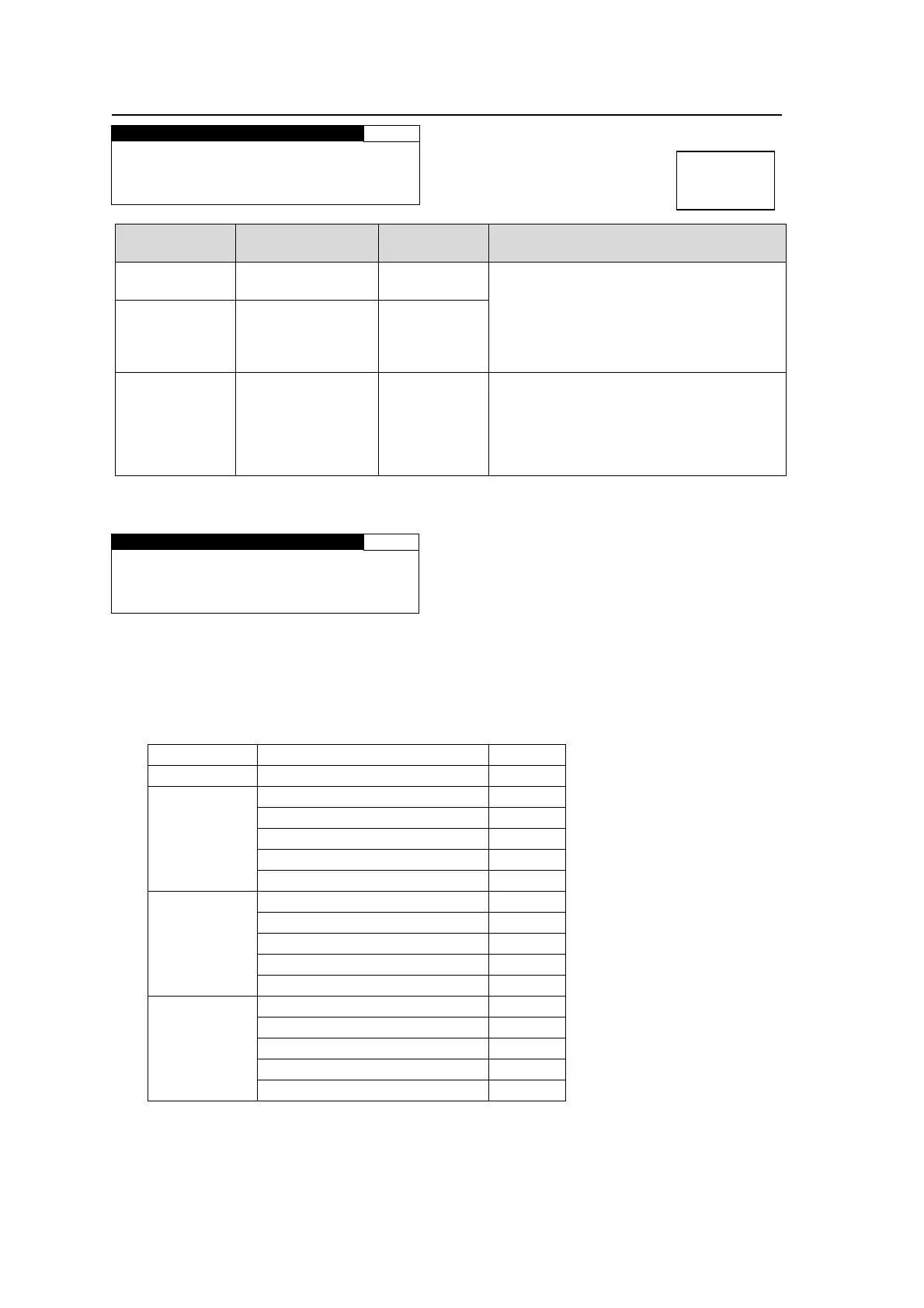
5-10-7. SD PHASE SET
SD PHASE SET 97
H PHASE: 0CLK
V PHASE: 0LINE
SC PHASE: 0.0°
Parameter Default
Setting range
(Steps)
Description
H PHASE
*1
0
-864 - 864
( CLK)
Adjusts the horizontal and vertical
phases of the system referring to genlock
signal. This setting is applied to SD
output signals.
V PHASE
*1
*2
0
*3
(FRAME, INPUT)
1
*3
(LINE, AVDL)
-313 - 313
( LINE)
SC PHASE
*1
0.0° -179.8°- 180°
Adjusts the subcarrier phase of comosite
and Y/C output signals referring to the
B.B. genlock signal.
Not adjustable with the tri-level genlock
signal. In such case, the menu will
appear as “NOT ADJUST”.
*1 The settings are not available if there is no reference signal input. In such case, the menu
as shown below will be displayed.
SD PHASE SET 97
H PHASE:NOT ADJUST
V PHASE:NOT ADJUST
SC PHASE:NOT ADJUST
*2 Set V PHASE to more than 1 line when setting SYNCHRO mode to INPUT.
*3 The default value varies depending on the SYNCHRO setting in section 5-10-1 “FS MODE
SET” and the IN SEL setting in section 5-7-1 “VIDEO INPUT SET” as shown in the below
table. The set value will be reset to its relevant default value whenever the SYNCHRO
setting is changed.
SYNCHRO IN SEL Default
FRAME ─ 0
LINE
SDI1, 2 1
COMPOSITE (525/60) 3
COMPOSITE (625/50) 4
COMPONENT (Y/C) 4
COMPONENT (others) 1
AVDL
SDI1, 2 1
COMPOSITE (525/60) 3
COMPOSITE (625/50) 4
COMPONENT (Y/C) 4
COMPONENT (others) 1
INPUT
SDI1, 2 0
COMPOSITE (525/60) 2
COMPOSITE (625/50) 3
COMPONENT (Y/C) 4
COMPONENT (others) 1
Menu button
VIDEO SYS
AUDIO SYS