CX2550/60/70 M4 Upgrade and Maintenance Manual 245
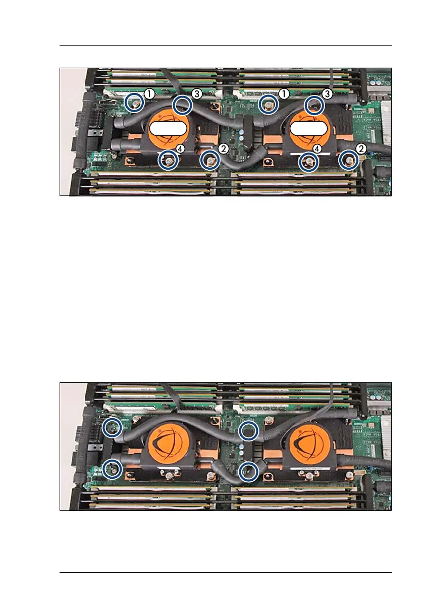
Figure 142: Installing the LC heat sinks (A)
Ê For CPU 1 and CPU 2 LC heat sink, proceed as described below:
Ê Carefully seat the heat sink onto the CPU socket.
I Take care of the pins. There is only one position which fits.
Ê Fasten the four captive screws (see circles) in the sequence printed on the
heat sink (1 to 4) by proceeding as follows:
Ê At first, fasten the four captive screws one by one (1 to 4) by hand
rotating them three turns.
Ê Then, fasten the four captive screws one by one (1 to 4) by hand until the
screws are completely tightened.
Figure 143: Installing the LC heat sinks (B)
Ê Fasten the screws of the VRM heat sinks (see circles).
 Loading...