GE HEALTHCARE
DIRECTION 2307224-100, REVISION 6DISCOVERY LS SYSTEM SERVICE MANUAL
Chapter 6 - Table Page 119
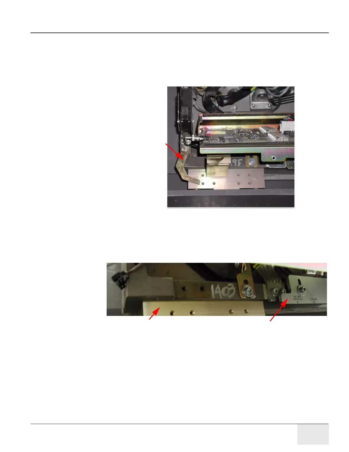
3.) Refer to Figure 6-9. Remove the characterization bracket, located near the fans on the right
front corner of the ETC chassis.
a.) Use a 5 mm Allen wrench to remove the M6 socket-head cap screw that fastens the
characterization calibration bracket into place. (Bracket is silk-screened: LOWER LIMIT
SWITCH and LOWER CHAR POINT.)
b.) Discard the bracket.
Figure 6-9: Characterization Calibration Bracket
4.) If necessary, modify the Calibration Bar:
a.) Refer to Figure 6-10. Locate the Calibration Bar fastened to the right side of the table
casting, beneath the ETC assembly.
b.) Fasten the bar back into place with the original M6 hardware.
Figure 6-10: Calibration Bar with Tab
Calibration Bracket
Remove this tab (interferes with the
CT-PET Latch Assembly attaches
to this bearing block.
CT-PET Latch Assembly).