GE HEALTHCARE
DIRECTION 2307224-100, REVISION 6DISCOVERY LS SYSTEM SERVICE MANUAL
Chapter 6 - Table Page 125
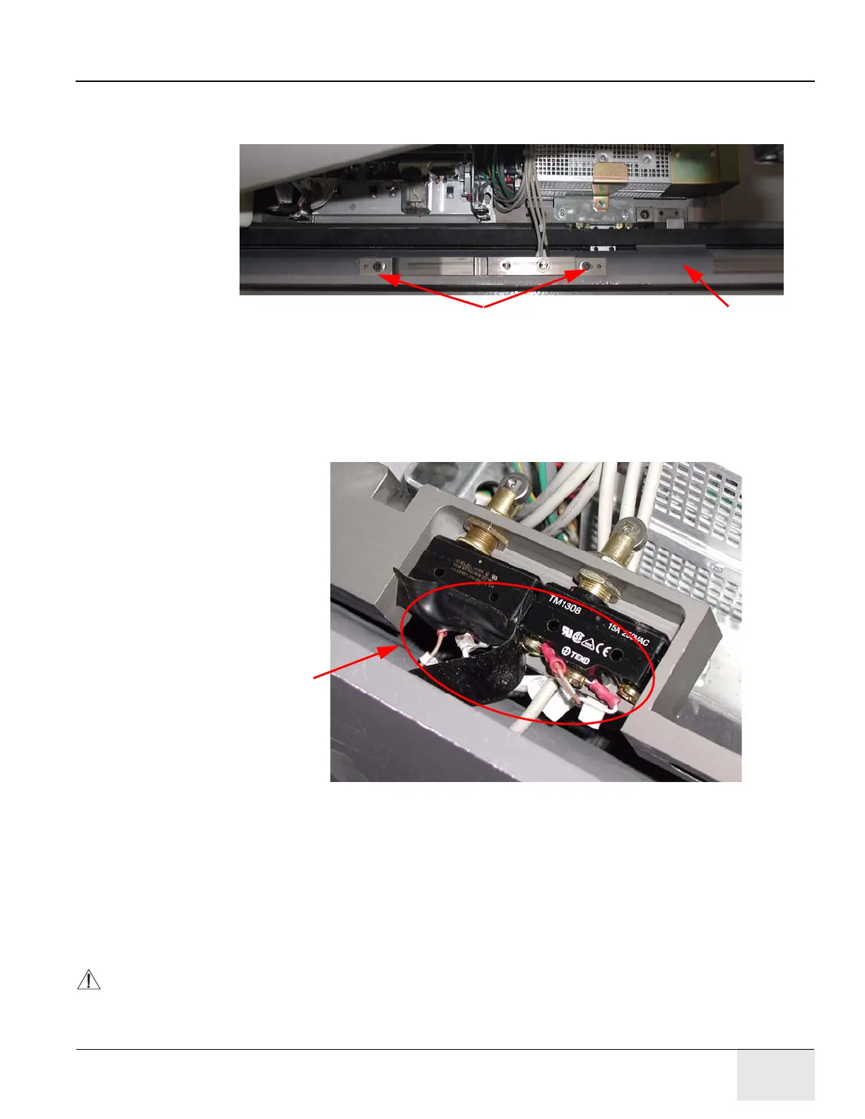
3.) Refer to Figure 6-17. Use a 6 mm Allen wrench to remove the CT and PET position limit
switches from the table. (Each limit switch fastens to the table with two socket-head cap
screws.)
Figure 6-17: CT Position Switch
4.) Refer to Figure 6-18. Disconnect the cables from each limit switch.
a.) Cut the wires from the terminals on the bottoms of the switches to facilitate removal of the
corresponding cables. (Cables are removed during Section 6.2.5.7.)
b.) Follow local guidelines to discard or recycle the PET and CT limit switches.
Figure 6-18: Cut Wires to Remove Switches and Cables
6.2.5.6 Remove the Switch Rail
1.) Use a 5 mm Allen wrench to remove the two M6 socket-head cap screws that fasten the front
of the switch rail (very heavy) to the table base.
2.) Use a 4 mm Allen wrench to remove the two flat-head screws that fasten the rear of the switch
rail to the table base. (The rail may be mounted with metal shims. Remove any found.)
3.) Follow local procedures to discard the pedal switch components.
CAUTION To prevent damage to the ETC from static discharge, ALWAYS wear a grounded wrist band
when disconnecting cables from the ETC Board assembly.
Socket-Head Cap Screws
Remove the switch rail.
Wires