GE HEALTHCARE
DIRECTION 2307224-100, REVISION 6DISCOVERY LS SYSTEM SERVICE MANUAL
Chapter 6 - Table Page 173
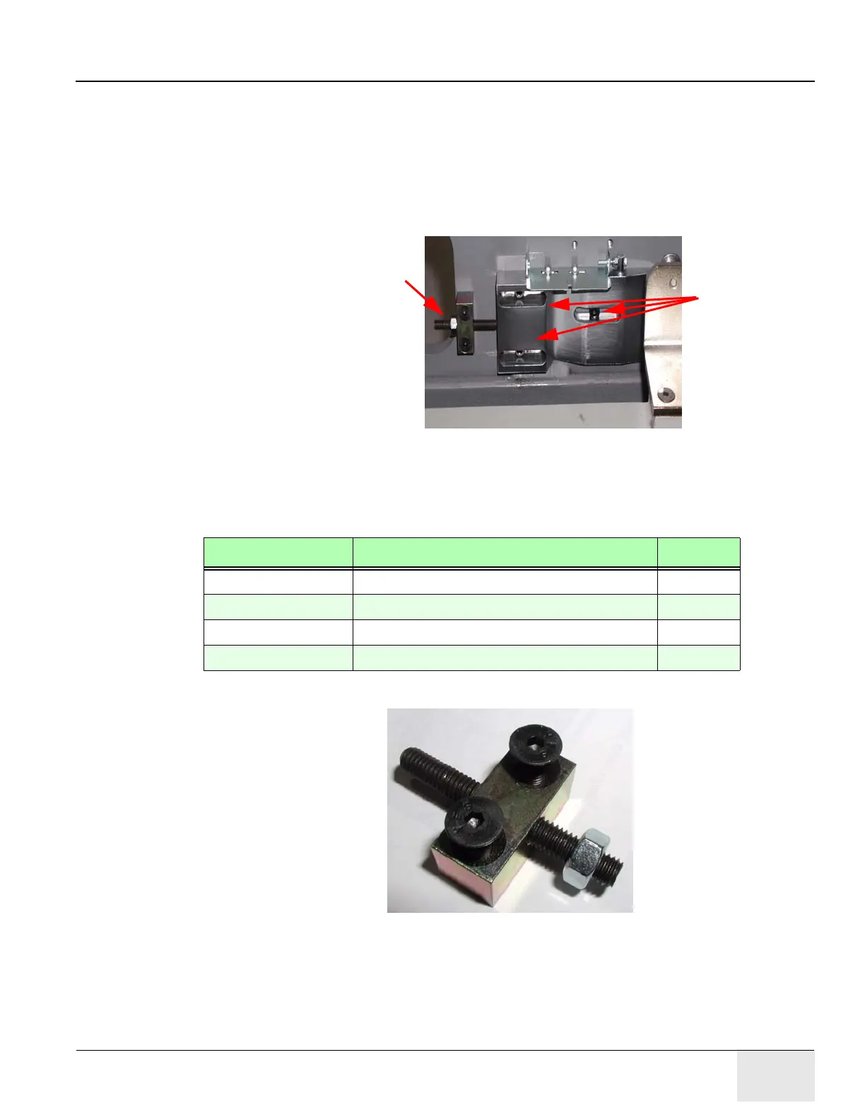
4. Refer to Figure 6-87.
a.) If necessary, loosen the flag hardware, and turn the adjusters to center the flag over the
notch in the CT and PET detent.
b.) Measure the distance between the leading edges of the CT and PET flags.
c.) If necessary, slightly loosen the PET detent hardware, and turn the PET Detent Adjuster
until the distance equals the value entered on page 113.
d.) Tighten the detent hardware.
Figure 6-87: Adjust PET Detent for Recorded Distance Between Scan Planes
6.2.6.33 Assemble and Install PET Detent Adjuster
1.) Locate and remove the following parts from the upgrade kit:
2.) Refer to Figure 6-88. Use the illustration as a guide to assemble the PET detent adjuster.
Figure 6-88: PET Detent Adjuster, P/N 2332092
Slightly loosen
detent hardware.
Turn screw to adjust distance
distance between PET and
CT detent locations.
Part Number Description Quantity
2332092 Adjuster Basis (Block) 1
2103580-46 M5 x 20 mm Flat-Head Countersunk Screw 2
46-328425P2 M6 Hex Nut 1
2345323-2 M6 x 50 mm Set Screw 1