GE HEALTHCARE
DIRECTION 2307224-100, REVISION 6DISCOVERY LS SYSTEM SERVICE MANUAL
Page 122 Chapter 6 - Table
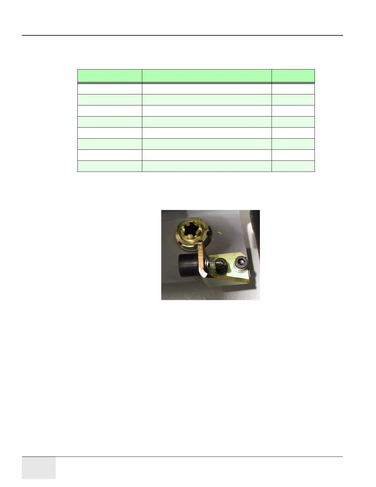
Note: The kit may contain a pre-assembled mechanical stop. If not, use Figure 6-13 as a guide to
assemble a mechanical stop for your system.
If the table has no mechanical stops, locate and remove the following parts from the kit:
4.) Use Figure 6-13 as a reference, and assemble the Rear Stop.
a.) Use the M6 hardware to assemble the bumper.
b.) Use the M8 hardware to fasten the mechanical stop to the rear location.
Figure 6-13: Mechanical Stop Bracket (In Rear Stop Location)
6.2.5 Remove the Manual Control Hardware
Follow the instructions in this section to remove the hardware and cables used to control the
secondary base of the ME1 table.
6.2.5.1 Remove the KB Box
The KB Box provides the electronics to drive the secondary base between the PET and CT
positions. The KB box controls the clutch motor assembly, mounted directly beneath it. Follow the
instructions in this section to remove the KB box. Follow the instructions in Section 6.2.5.10 to
remove the entire Clutch Motor assembly and casting.
Part Number Description Quantity
2306559 Back Stopper Bracket 1
2334772-2 Bumper 1
46-214695P79 M8 x 20mm Socket-Head Cap Screw 2
2109878-8 M8 Flat Washer 2
2315373-5 M8 Lock Washer 2
46-328425P2 M6 Nut 1
2109878-3 M6 Washer 1
2315373-4 M6 Lock Washer 1