GE HEALTHCARE
DIRECTION 2307224-100, REVISION 6DISCOVERY LS SYSTEM SERVICE MANUAL
Page 212 Chapter 6 - Table
e.) Select MECHANICAL CHARACTERIZATION.
f.) Select BASE, and follow the on screen instructions.
g.) Manually push the table to the CT position. If the table is already in the CT position, push
it off the detent and push it back into place.
h.) Press the cradle release button to energize the clutch motor.
i.) Click CONTINUE.
j.) Press the Cradle Release button, and push the table to the PET position.
k.) Press the Cradle Release button to re-energize the clutch.
l.) Click CONTINUE.
m.) Click SAVE & CONTINUE.
22.) Run another hardware reset from the Service Desktop.
23.) Refer to Section 8.1.1 on page 243 to run VQC.
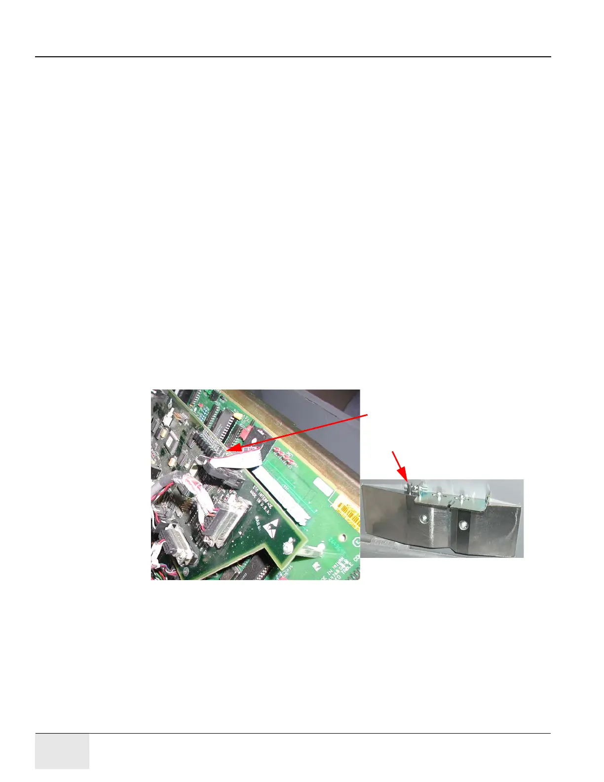
24.) Refer to Figure 6-141. Fine tune the PET and CT flag positions.
a.) Use the gantry control pushbutton to drive the base to the CT position.
b.) Refer to Figure 6-142. Use a 2.5 mm Allen wrench to slightly loosen the two socket-head
cap screws that fasten the flag plate to the detent.
c.) Face the head of the screw, and use a 2.5 mm Allen wrench to turn the adjusting screw
counterclockwise until LED DS13 on the ETC I/F board turns Off.
Note: The ETC cover can be removed, but the LED can be viewed with the cover in place.
d.) Turn the adjusting screw clockwise until LED DS13 just turns On.
e.) Turn the adjusting screw two additional turns clockwise.
f.) Drive the table base to the PET position, and repeat Step b through Step e.
Figure 6-141: Final PET and CT Flag Adjustment
Observe LED, DS13.
Adjusting Screw