GE HEALTHCARE
DIRECTION 2307224-100, REVISION 6DISCOVERY LS SYSTEM SERVICE MANUAL
Page 324 Chapter 12 - Troubleshooting
5.) Check the ETC Interface J7 (Pins 11 and 12). Verify that when the [Cradle Release] button is
pressed and released on the control panel, the voltage changes as follows:
• Button pressed: 24 VDC
• Button released: 0 VDC
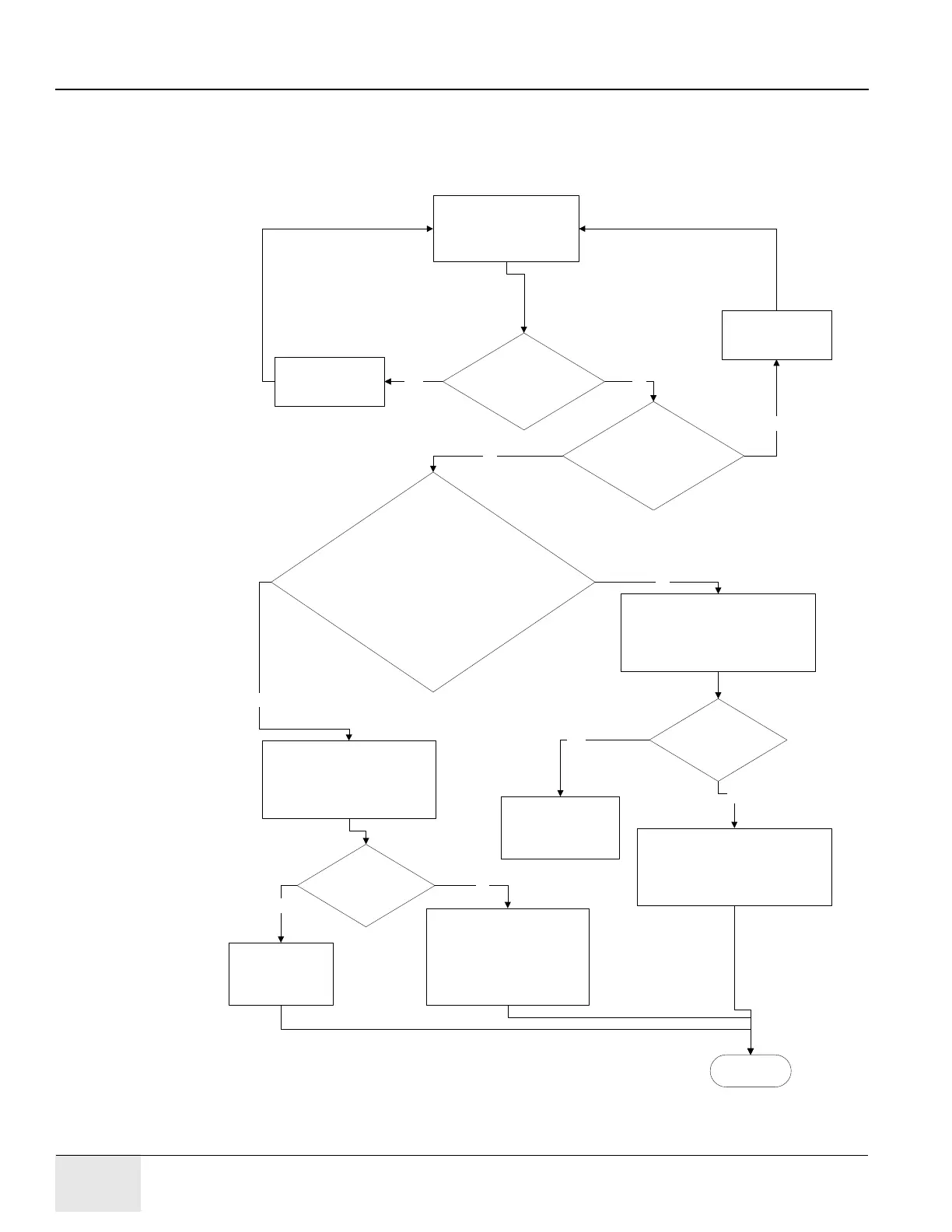
Figure 12-5: Troubleshooting for Clutch Fails to Engage/Disengage (Automated Tables)
Clutch fails to engage/
disengage
yes
Check the FUSE F1 on the
Clutch Driver Unit, is it blown ?
no
Replace the FUSE
yes
Does the SSR LED(which is found on the SSR in the
Clutch Driver Unit) toggle on and off when you press the
Cradle Release button on the Control Panel several
times?
no
Perform a voltage measurement on
J221 between pins 1 & 4 (on the
Clutch Driver Unit).The voltage
should change from 0Vdc to 130Vdc
when you press the Cradle Release
button.
Check the cables in the path from the
ETC I/F J7 to the Clutch Driver Unit
including the ETC Card
PNs:
1. 2340737
2. 2338086
yes
no
Check all the cables in the path
including the Clutch.
PNs:
1. 2340390
2. 2309059
3. 2323726
4. 2323727
Does the voltage
change between 0 to
130 Vdc?
The malfanction is in
the SSR or the
connection between
the SSR and the
J221 Connector
yes
no
Measure the voltage on cable 2338086
J18 side, between pins 1 & 3. The
voltage should change from 0Vdc to
24Vdc when you press the Cradle
Release button.
Does the voltage
change between 0 to
24 Vdc?
no
The malfanction is in the
SSR or the connection
between the SSR and
the J18 Connector
yes
End of test
Is E-STOP circuitry
activated or Cradle Release
button pressed?
Reset the E-STOP
circuitry or press the
Cradle Release button
yes