GE HEALTHCARE
DIRECTION 2307224-100, REVISION 6DISCOVERY LS SYSTEM SERVICE MANUAL
Chapter 7 - Gantry Page 235
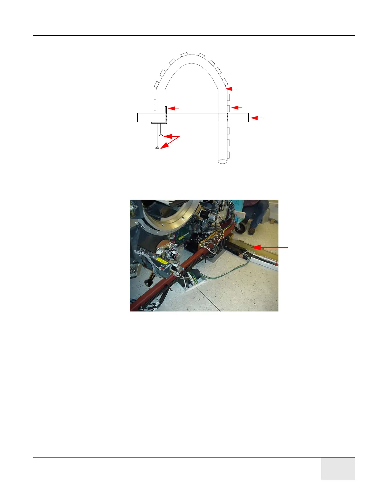
8.) Refer to Figure 7-14 and Figure 7-15. Fold the retractor and connect the bracket to the legs
crossbeam using four M6 x 20 mm screws.
Figure 7-14: External Retractor Connected to Legs Crossbeam
Figure 7-15: External Retractor and Cables
External Retractor
Clips
Legs Crossbeam
Bracket
Length of
Protruding
Cable
External
Retractor