GE HEALTHCARE
DIRECTION 2307224-100, REVISION 6DISCOVERY LS SYSTEM SERVICE MANUAL
Page 178 Chapter 6 - Table
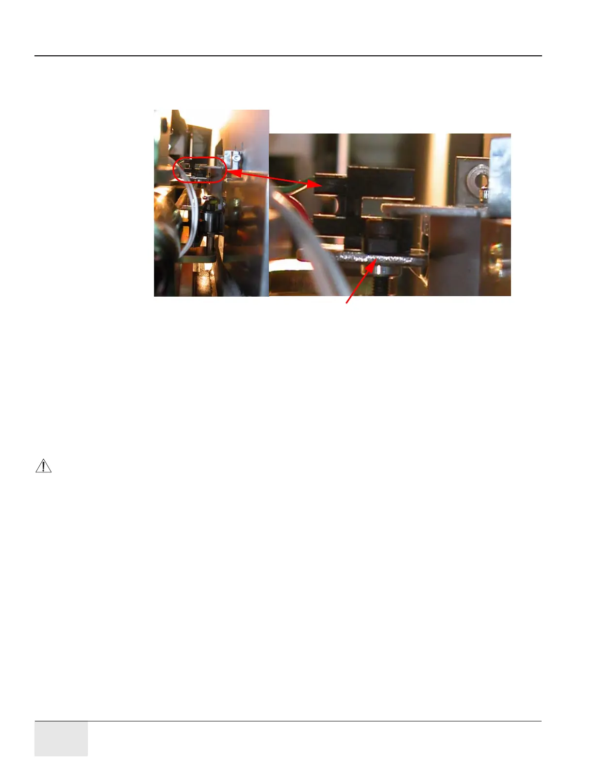
5.) Refer to Figure 6-95. Check for clearance between the optical sensor and the flag plate. (Refer
to Figure 6-94. If the optical sensor touches the top or bottom surface of the flag plate, bend
the optical sensor bracket until the distances from the sensor to the flag plate surfaces appear
equal.)
Figure 6-95: Align the Optical Sensor to the Flag
6.) Refer to Figure 6-94. Carefully swing the optical sensor back to the starting position.
7.) Slowly move the table into the CT detent.
8.) Swing the optical sensor back into place and check the clearance between the sensor and the
surfaces of the CT flag plate. (Refer to Figure 6-94 and Figure 6-95. If the optical sensor
touches the top or bottom surface of the flag plate, bend the optical sensor bracket to move
the sensor away from the surface of the flag plate.)
9.) If the optical sensor bracket was adjusted at both detents, repeat Step 2 through Step 9 until
the optical sensor clears both flag plates.
NOTICE It is more important to clear both flag plates without interference than it is to have equal
clearances between the optical sensor and the top and bottom surfaces of the flags.
10.) Use a 3 mm Allen wrench to secure the optical sensor to the bracket with two M3 x 10 mm
socket-head cap screws.
Bend this bracket to adjust optical sensor position.