GE HEALTHCARE
DIRECTION 2307224-100, REVISION 6DISCOVERY LS SYSTEM SERVICE MANUAL
Chapter 7 - Gantry Page 231
11.) Grease the end of the trapezoidal screw, insert the tracking trapezoidal screw into the flange,
and assemble the unit on the adjustable baseplate using three M6 x 10 mm screws. Loosely
tighten these screws.
12.) Measure the distance between the tracking trapezoidal screw and the linear bearing at both
ends, and correct the positioning until the distances are equal and the tracking trapezoidal
screw is parallel to the linear bearing. (This prevents the screw from seizing up.)
13.) Tighten the three M6 x 10mm screws.
14.) Connect the nut holder to the gantry back beam using four M6 x 16 mm screws.
15.) Drive the gantry back and forth on its rails to ensure that the drive mechanism is functioning
properly.
7.5.2 Gantry Cables or Retractor Replacement
If it becomes necessary to replace a cable or a retractor, see the following installation instructions
and locate the part needed to be replaced.
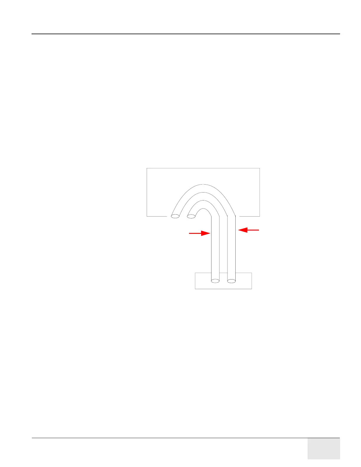
The external PET cables and the new CT-PET cables are routed through two retractors (external
and internal) as illustrated in Figure 7-9.
Figure 7-9: Retractor Assembly
Gantry Bulkhead
Internal
Retractor
Retractor
External
Retractor Static Bracket