GE HEALTHCARE
DIRECTION 2307224-100, REVISION 6DISCOVERY LS SYSTEM SERVICE MANUAL
Page 202 Chapter 6 - Table
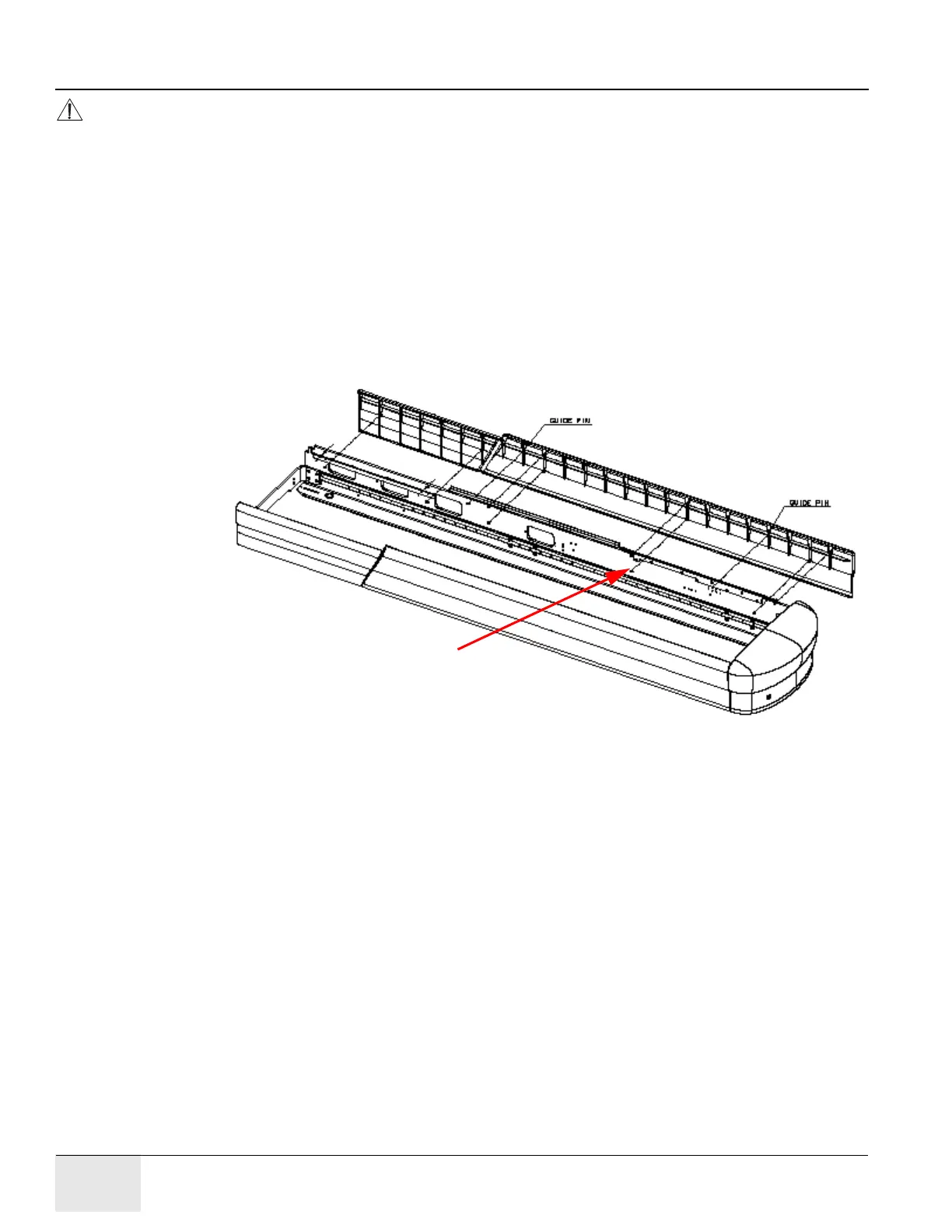
CAUTION Refer to Figure 6-129. Do NOT install the bottom cover screw between the PET and CT
Detents, on the right side of the table. This screw will interfere with the table travel between
the two positions, causing the table to jolt as the latch rolls over the head of the screw.
Recommended: Fill this hole with RTV to prevent it being used.
You may install a screw in the corresponding hole in the left rail.
3.) Refer to Figure 6-129. Use a 3 mm Allen wrench to fasten the side covers into place with the
following M4 hardware:
• M4 x 20 mm socket-head cap screw (SHCS), P/N 46-328417P6
• M4 lock washer, P/N 46-328432P2
• M4 flat washer, P/N 46-328430P2
4.) Use six sets to fasten the left cover into place. Use five sets to fasten the right cover into place.
Fasten the hardware until just snug. Do not over torque.
Figure 6-129: Side Covers - Exploded View
5.) Attach the Front Left and Right Side Covers to the secondary base with four sets of the same
M4 hardware used to fasten the longer side covers into place.
a.) Use a 3mm allen wrench to fasten the front covers into place.
b.) Refer to Figure 6-129. Attach the front covers by the bottoms only. (The cover guide
hardware occupies the top set of through holes.)
Do not install this screw.
Recommended: Fill this hole with RTV.