GE HEALTHCARE
DIRECTION 2307224-100, REVISION 6DISCOVERY LS SYSTEM SERVICE MANUAL
Page 144 Chapter 6 - Table
6.2.6.12 Install the Base Axis Motor I Cable (P/N 2323724)
Install the Base Axis Motor I Cable between J11 on the rear of the table bulkhead and the J5
connector on the Cradle Tilt/Elevation Driver Assembly.
1.) Insert the three-pin connector through the J11 opening at the back of the Table bulkhead.
2.) Attach the cable labeled Base Axis Motor R to the J11 connection on the front of the Table
bulkhead.
3.) Route the J11 cable from the main table harness cable to the Elevator/Tilt Drive PCB. (Do not
tie-wrap at this time.)
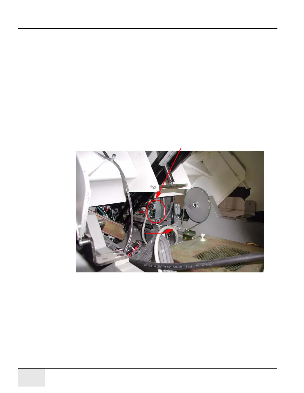
4.) Refer to Figure 6-41. Fasten the cable connector to J5 on the driver assembly.
For best results, kneel on the right side of the table and reach through the scissor assembly
and across to the left side of the table to attach the J5 cable. Reach in the direction shown in
the illustration.
5.) Refer to Figure 6-41. Pull the cable toward the front of the table to clear the heat sink.
6.) Reattach the Cradle Tilt/Elevation Driver cover, and use a 1/8 inch Allen wrench to fasten the
four cover screws on the cover.
Figure 6-41: J5 Location on Cradle Tilt/Elevation Driver PCB
J5 Location (Viewed from Left, Front of Table)
Kneel on this side of the table and reach across.
Ground Stud